Sunday, January 29, 2017

A Simpson's Supremacy Model No. 103.23180 Wood Lathe


A relic from the 1940s or '50s, this is the Canadian version of a Sears Craftsman machine bearing the same model number.


The above photo shows it part way along to restoration, along with a cabinet stand that I've made for it. Here are views of the I.D. plates.


Simpson's was the Robert Simpson Co., which partnered with Sears in 1952 and sold the Craftsman line of tools in Canada. The machine pictured here would later have been branded Craftsman, as it always was in the USA.

I picked up this item off Kijiji. Much of it is in pretty good condition, but there are some flaws to be corrected, and some missing pieces that I'll have to come up with replacements for. Permit me to give you a tour of the machine as it currently stands.

The Lathe Bed

Aside from the grime, splotches and discolouration, this is a thing of beauty.


It's undamaged. The machined ways exhibit only the slightest bit of surface rust. The structure has five cross-ribs underneath, so it's a sturdy, rigid affair that's truly fit for its duty. It attaches to a work surface by way of three 5/16" bolts.

The Tailstock

The tailstock's position clamp, ram and handwheel are complete, but there are three items missing from the tailstock:

  • The ram's 5/16"-18 locking screw is supposed to have a handle attached to its head, so that a wrench is not needed. I'll fabricate a knob-headed screw from a suitable knob that I have on hand, and some threaded rod. I'll have to machine a dog point on the end of the threaded rod to make it proper.
  • The tailstock's centre is missing its centre. The centre is an MT1 shank with a hollow end that's meant to accept a small, tapered centre point. I can get an MT1 dead centre from KBC Tools & Machinery. Busy Bee lists an MT1 live cup centre on their website. I'll probably end up getting both. A 1/2" drill chuck for the ram would be nice to have as well.
  • The lathe would have originally come with a 3/4" wrench for tightening the tailstock's position clamp, and the tool rest's banjo. That's long gone. I'll get a low-end 3/4" combination wrench from Princess Auto to replace it.
The Tool Rest

It's a sturdy 8" tool rest in good condition.


The Headstock

And here's where all the real trouble resides.


There's quite a lot to tell about this item; I scarcely know where to begin. I'll just list the headstock's features/characteristics/problems in no particular order.

The Pulley And The Indexing Feature

The pulley in the photo is a standard replacement 4-step pulley with a 3/4" bore. The original pulley was missing from the lathe.

The large diameter face of the original pulley had 36 holes in it which, in conjunction with a spring-loaded, retractable pin, provided the lathe's indexing feature (an index stop at every ten degrees). Needless to say, the indexing feature is now inoperative, although the spring-loaded, retractable pin is fine. I have an idea how I might recreate the feature with a separate indexing disc. I'm not certain that it will be doable. We'll see.

The Bearings

The bearings are 3/4" bore x 1" O.D. x 1" long porous bronze sleeves. They're actually not in bad condition for bore size and roundness, but the inboard bearing has some nasty looking scoring in its bore. I have replacements on order -- I'll replace both bearings.

For a thrust bearing, the lathe originally had a ball-thrust bearing that apparently resided inside the headstock casting at the outboard end. That bearing is missing. I'll replace the thrust bearing's function with a collar and a bronze thrust washer at the inboard end of the spindle. I won't be using the collar that's in the above photo -- I'll get a more suitable steel collar from Princess Auto.

The Spindle Nose

It's not threaded. I believe that a later version of this lathe had a threaded spindle nose, but this early machine just has a flat for set screw attachment of an accessory like a face plate. Good luck finding a face plate to fit such an arrangement. I'll have to see if I can fabricate a face plate somehow.

The spindle's bore takes an MT1 taper. A spur centre came with the lathe, so that's taken care of.

The Spindle

It's remarkably undersize in diameter -- it's 0.741". (Nominally, it should be 0.750".) That mystifies me. It makes for a pretty sloppy bearing fit. It works, but the bearings have to be generously oiled, else they're prone to run noisily.

The spindle's undersize condition also made for a lot of radial pulley run-out with a standard, 3/4" bore pulley installed. I solved that problem with a serendipitous piece of shim stock, and the pulley now runs reasonably true.

The Headstock's Front Cover

There isn't one, though there's supposed to be. The headstock would originally have had a sheet metal cover for that gaping opening in front. I'll have to fabricate a replacement; that'll be a bit of a challenge.

The Paint

It's pretty old and tired and beat up looking. The best I'll be able to do for a near match to the original will be to repaint it Tremclad grey. That'll be a gloss finish. I'd rather it be a satin or matte finish, but those don't seem to be available in a suitable enamel.

Anyway, there's what I have to work with. On with the restoration.

Motor Wiring

It's pretty straightforward. The Home Depot has everything that's needed, except for maybe a 5/16" cable clamp and 1/4" spade terminals -- I had those on hand.


I dislike extension cords, so I fit out machinery with power cords of a decent length. I find that four metres of 16 AWG SJOOW line cord is ideal for fractional horsepower installations. In this instance, after subtracting the length of cord from the switch to the motor, I was left with a power cord length of about 11 1/2 feet.

Nothing special in the way of a switch is needed for fractional horsepower motors. A common Leviton 15A toggle switch serves nicely.

Note the cable clamp in the second photo above. I was taking no chance that the motor's power cord might ever meet the v-belt.

The Motor

I'm using a 1/3 hp furnace fan motor. 1/2 hp is ideal for a typical wood lathe, but 1/3 hp is adequate. No one is going to be turning porch columns on this lathe.

A TEFC (totally enclosed fan cooled) motor would be nice, but those are costly items. The motor shown in the above photo will do.

- - -

So there we have the current state of the lathe. This blog post is getting rather long, so I'll start a new post for the restoration information

# # #


# # #

Wednesday, January 25, 2017

Tool Review -- Lee Valley's Non-Electric Branding Iron

My son got me this for Christmas, and I'm delighted with it.


In two lines it says,
"ROUGE RIVER WORKSHOP
THOMAS GASPICK".

The machining of the brand's face is exquisite, and the tool works as advertised. There is some skill to using the tool, though, and that can only be acquired with practice. Try the brand out on scrap material before applying it to anything that matters to you. The skill is in getting the thing straight, and applying sufficient overall pressure so as to produce a uniformly burned image. It seems to help to rock the tool very slightly from side to side, and from top to bottom. Be careful that you don't let the brand lift at all while rocking it -- you're liable to produce a somewhat doubled impression. Here's a view of three of my practice brands that illustrates some of the pitfalls.


All three are marginally acceptable. The upper one is a little bit overdone, but it's the best. The other two suffer from near-voids. (The bottom one would have been perfect had I leaned just a little harder on the right side.)

The instruction sheet that comes with the brand is quite adequate. The sheet calls for 1 - 3 minutes of heating with a propane torch. I've found that 3 minutes with a moderate flame produces a reliably heated brand. At first, you're probably better off to err on the side of overdoing your impression, rather than be afraid of the tool and get an impression with voids.

# # #


# # #


A TecoMaster 10" Radial Arm Saw


I got this off Kijiji yesterday.


As you can see, it's still on my vehicle. I'll enlist my wife's help later today, and see if the two of us can manage to safely lift it out; the thing is HEAVY!

The machine dates back to the mid 1960s. I was a teenager back then, and I had one like the one pictured for a while. I ended up returning it to the store because its accuracy and repeatability were disappointing. As I learned later, practically all radial arm saws suffer from extreme difficulty of fine adjustment, and iffy repeatability.

So what's behind my buying a piece of gear that I long ago rejected? Nostalgia, I guess -- trying to recapture my long lost adolescence. The saw may end up as nothing more than a firewood saw, but that's ok --at least I'll have a piece of my youth back, for whatever that's worth.

- - -

Progress So Far -- WEDNESDAY, MAY 3, 2017

I've been remiss in not documenting what I've been up to with the saw. I've dismantled it down to its component sub-assemblies, and rigged an old machine stand for it to perch on. Here's a view of the saw's base frame mounted on the stand.


I don't have space in my shop for it; it's going to have to live outdoors on the patio, with a tarp over it for protection from the elements when it's not in use.

The machine is massive in all of its elements. The base frame is a heavy gauge weldment of great rigidity.

What I mean to do is dismantle and clean/inspect/lubricate all the pieces, then reassemble the saw into the best radial arm saw that I can make of it. That may take a while -- there's quite a lot to the machine.

The Column

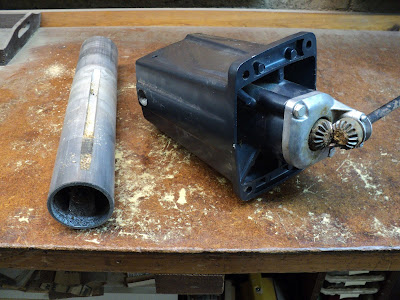
Here's the column off on its own.


It fastens to the base frame with four 3/8"-24 x 1" bolts, with hex nuts and split lockwashers.

At the rear of the column, there's a key affair that engages a groove in the post, so that angular play can be adjusted out of the post.


Here's the 3" diameter post cranked fully out of the column's base.


There's a wad of sawdust packed into the lower end of the post's groove.


Here's how that area is supposed to look.


Here's a close-up view of the elevation bevel gearing.


And here's the gearing dismantled, and the elevation screw out of the column.


That screw is 8 tpi, and the gear ratio is one-to-one, so each revolution of the elevation crank yields 1/8" of vertical post travel. The screw's thread is left-handed, so crank operation is intuitive; i.e. clockwise = raise.

Now what I have to do is --
  • Clean and degrease everything.
  • Paste wax the post and its bore for protection.
  • Reassemble with fresh grease on the elevation screw. I won't grease the exposed gearing, that'll just attract and hold sawdust.
  • Reinstall the column on the saw's base frame. Once that's done, I can go on to tackle the radial arm.
- - -
The Radial Arm -- THURSDAY, MAY 4, 2017

Here's a view of the rear end of it, with the top cover and the degree indicator wheel removed..


That semicircular item down in front is the detent block that provides the 0° and left and right 45° detents for the arm's swing.

Here's the front end of the arm with the front cover removed.


The long cover with the rip scales on it just slides off the front, and we can see the arm casting that carries the track.


I'd rather not have to take all that apart, but it appears that I'm going to have to. The detent pawl seems to be seized from disuse. From the appearance of the detent block, I don't think this saw was ever taken off its 0° detent. The only way to get at the pawl is to remove the track from the arm casting.

The Carriage -- SATURDAY, MAY 27, 2017

Here's a view of the top of the carriage less the yoke and motor/transmission unit.


The stud at the centre-right is the nut for the carriage travel lock screw. The lever at the centre-left is the detent for carriage swivel.

The bearings are marked "HEIM-553A". I can find no reference to that on the internet. There are HEIM bearings though, mostly rod ends.

The two left side bearings are fixed in place -- they're not adjustable. The two right side bearings are mounted on eccentric studs -- they're adjustable for elimination of play between the carriage and its rail. That adjustment had best be made while the carriage is as pictured, without the yoke and the motor/transmission unit attached to it.

- - -

Update -- FRIDAY, JUNE 21, 2019

I've been remiss here, as I sometimes am. I never kept up the above post to completion.

To make a long story short, I did get the saw into good working order, fitted out with a capacious particle board table. The saw served me well in the construction of a small woodshed.

The saw had to reside outdoors with a tarp over it, and that didn't work out too well at all. Here are views of the saw's current state after two years of idleness.


Those cheap, low-end tarps aren't worth the powder to blow them to hell. The particle board table got soaked and stayed soaked -- it's a ruin. I have enough material on hand to make a replacement table.

What I don't have is a good site for the saw. The saw needs to be indoors, and that's not on around here. A radial arm saw also needs lengthy clearance at either side to facilitate rip cuts, and even my outdoor site doesn't provide that; there's a small shed in the way at either side.

So, there's not much left to do but to get rid of the thing. I suppose I should fabricate a new table from the material I have on hand. If I put the saw up for sale 'as is', I'll be lucky to get twenty bucks for it.

- - -

Done And Sold -- THURSDAY, JUNE 27, 2019

Here's the saw with a new table.


I've left table alignment and scoring for its next owner. Table alignment on this machine is a nightmare. There is no provision for fine angular adjustment of the radial arm -- the table must be tweaked in order to achieve saw-path-to-fence perpendicularity. That's difficult to do, to say the least.

Anyway, the saw sold for $60.00 CDN. Three big guys with a huge van came for it in response to a Kijiji ad. So, that went well, and I'm rid of the thing.

# # #


# # #

A Bowl

In keeping with my ongoing project to learn wood turning, I set myself a faceplate turning exercise. Here's the result.


That bowl profile is my recollection of a bowl that I made in grade 7 or 8 wood shop at school. It's not a bad outcome for a first attempt after about fifty years. I think the one I made in school was better, though.

I've stained it on the lathe with Minwax's Cherry 235 Wood Finish, after applying Minwax's Pre-Stain Wood Conditioner. I'll give it a few coats of tung oil for a final finish.

# # #


# # #


Friday, January 13, 2017

An Angel


Height is almost 11"; head diameter is 2"; diameter at base is 2 7/8".

Body is lilac wood; wings are pine. Finish is a single application of tung oil.

Lilac is quite a dense wood. The thing weighs 17 ounces -- just over a pound.

I plagiarized the body/head profile from a picture I came across in Google Images. The wings are my own design. The big flaw at the base makes it an angel with a swirling skirt.

- - -

A friend of my sister-in-law's mentioned that she'd like to have an angel, so I set about making an angel. We'll see if she likes it. If she likes it, she's welcome to it. If not, it can stay here and be our house angel.

* * *

Update -- FRIDAY,  AUGUST 25, 2017

The wings came off.

I knew they were fragilely attached, but I thought they'd be ok so long as the angel was kept standing upright, and handled carefully. I suspect that the angel was stored for a spell on its back after it left my hands, and the stress on the wings was more than the glue joins could bear.

I bored 1/8" diameter holes through the narrowest portions of the wings, then re-glued the wings to the torso with CA adhesive. Once the adhesive had set (a few minutes) I bored the wing holes on into the torso 1/2" deep. Then I added dowel pins. The work shows, of course, but it's tolerable.


So now I have a re-winged angel that's only slightly more flawed than it was before.

- - -

This hasn't been a great success. I suspect that my sister-in-law wasn't much impressed by the angel, and she stashed it away and forgot about it until I asked after its fate. I doubt that the intended recipient ever saw the angel.

I don't think I'll return it to my sister-in-law. I'll just keep it here as our house angel.

# # #


# # #


Thursday, January 12, 2017

Power Bar Innards


'Ever wondered what's inside these things?


Wonder no more.


The answer is, "Not much."

The only costly components are the circuit breaker, the line cord and the bit of labour to solder the connections and assemble the thing. The rest of it is dirt cheap to the manufacturer.

# # #


# # #


Wednesday, January 11, 2017

Hardware Review -- Ikea 'Tertial' Articulated Lamp


I needed a work light for a wood lathe, and found this item at Ikea. I figured that for $9.99 CDN I'd give it a try.


It's made in China -- no surprise there. Evidently, one way Ikea keeps the price so low is by not even putting the thing in a box. It comes as you see it in the above photo -- in only a clear plastic bag, some assembly required. There are no colour options; it's only available in silver. Let's get it unwrapped and see what we've got.


The reflector installs with a push and a twist. There are two loose springs to be fitted, and the usual clamp-on base. And here we are all done up.


It works. Here it is installed at the lathe.


The lamp's reach is just barely adequate -- about what you'd expect from this class of lamp; I may move it closer to the lathe's headstock. For $9.99, it'll do.

- - -

A couple of observations about this type of lamp in general:
  • The rotary switches love WD-40. Drool a bit of WD-40 into a lamp's switch, and the switch will operate nicer and last longer.
  • I find the clamping arrangement for the swivel base affair to be a bit iffy for strength. Whenever possible, I like to take advantage of the fastening holes provided in the base, and screw the thing down. On the lathe stand pictured above, that was easy to do, and it makes for a much stronger lamp base attachment.
- - -
Update --  THURSDAY, JANUARY 12, 2017

I've noticed a flaw in the geometry of the upper pair of arm bars. The bars are supposed to remain parallel to one another, no matter how the lamp head is extended/positioned. They don't. They can go way out of parallel, like so.


That's not right; it limits the flexibility of the articulation. I have an elderly Luxo Activist lamp -- essentially the same construction -- and it operates correctly.


I suspect that there's a length error in one of the arm bars. I doubt that there's any practicable fix for it. The flaw isn't bad enough that I'll be moved to return the lamp, but it's disappointing, even for a $9.99 item. It's 2017 after all. How difficult can it be for a manufacturer to get his fundamental dimensions right?

# # #


# # #


Monday, January 9, 2017

Roll-Around Machine Tool Carts


One of the best ideas I've ever had for my small (300 sq. ft.) workshop was to mount machines on purpose-built shelving unit carts with casters. Here's a view of the one I made for my 9" band saw.


When the band saw is idle, I wheel it out to the rec room where it's out of my way. When I need the saw, I wheel it back into the shop and put it to use. The shelving underneath gives me much-needed storage space, and lets me keep the saw's accessories right with the saw.

The slightly out-rigged casters make the cart stable enough -- I don't find that the arrangement is at all 'tippy'; one would have to be trying in order to tip a cart. Following are some notes on the carts' construction.

Material

  • For the frames and shelves, the cheapest stuff I could find -- nominal 1" x 10" x 8' pine shelving planks from Home Depot. It's pretty rude, crude stuff but it serves.
  • For the back, 1/4" firply or RevolutionPly 5.2mm underlayment plywood. (I found the RevolutionPly product at Home Depot. It's ideal for the purpose, and the price is reasonable.)
  • For the outriggers, 2" x 3" for 2" diameter casters; 2" x 4" for 3" diameter casters.
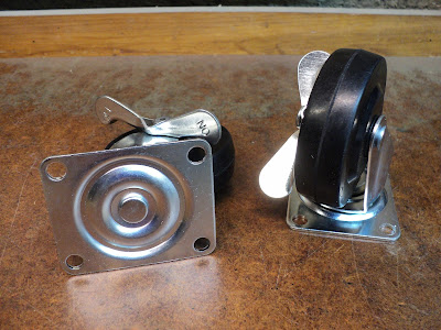
  • Casters: Absolute minimum 2" diameter. Busy Bee has a set of four with brakes, Cat. No. B17862, for $9.99 CDN. Better to go with 3" diameter casters -- Busy Bee Cat. No. B17863, $15.99 for a set of four with brakes.
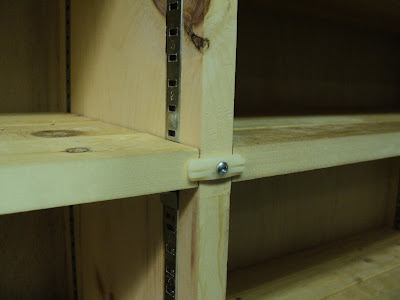
  • Shelving support hardware: Knape & Vogt 255 Series steel standards (pilasters) and clips.
Joinery

Simple butt joints at the corners, glued and screwed.


That's five No. 8 x 2" FH wood screws.I know that running screws into end-grain, as I've done here, is frowned upon in some circles, but it works fine -- my corner joints are quite sturdy.

The plywood back is simply glued and nailed on with finishing nails. I make the back slightly oversize, then flush trim it with a router.

Outriggers

For 2" diameter casters, I make the outriggers extend by 2". For 3" diameter casters, 3".

Shelving Pilasters

Set in 3/16" deep by 5/8" wide dadoes.

Lee Valley has the Knape & Vogt product. Home Depot and Canadian Tire carry a Rubbermaid equivalent that I advise against -- the Knape & Vogt product is superior, and about the same price. The Rubbermaid pilasters are poorly finished, and I've had a slot spacing defect in them once. I won't buy the Rubbermaid stuff again as long as I can get Knape & Vogt.

If shelves tend to 'walk'[1] or buzz because of machine vibration, a fix is to add 1/2" diameter inner-tube-rubber pads to the bearing faces of the clips. Here's a view of a bunch of clips that have had rubber pads added to them.


Cut the pads with a gasket cutter. Affix them to the clips with gelled CA adhesive.

Machine Attachment

Secure the machine to the top of the cart with suitable fasteners. Leaving a machine unsecured is not a good idea.

- - -

That about covers it. I've made five of these carts so far, and they're proving to be a very good thing for my workshop.

- - -

Note:

[1] Some machines are worse for this than others. A primitive wood lathe that I've mounted on a double-wide cart can really set shelves to 'walking', depending on lathe speed and how well balanced the item mounted in the lathe is. I came up with a quick-and-dirty solution in the form of nylon turn buttons installed on the cart's centre vertical divider, like so.


The turn buttons don't look too bad. The downside is that shelf relocation is complicated a bit by having to relocate a turn button as well.

# # #


# # #

Hardware Review -- Busy Bee 3" Caster Set, Cat. No. B17863


At $15.99 CDN for the set of four, these are a good deal. I've been putting them on roll-around tool carts that I've been making lately, and they appear to be entirely fit for the purpose. They roll and swivel smoothly; the brake feature works well, and engages/disengages with little effort. I'm quite pleased with them.

The mounting plates are 2 3/8" x 2 7/8". The mounting fastener holes are 5/16" diameter. Overall height is just shy of 3 5/8".

(Busy Bee also has a two inch wheel diameter version, Cat. No. B17862 -- $9.99 CDN for a set of four.)

# # #


# # #

Saturday, January 7, 2017

Straightedges -- Sometimes Tools Are Where You Find Them


I came up with two very nice straightedges recently, from an unlikely source. Here's a view of them.


And here's a close-up view of an end, to give you an idea of the cross-section.


The cross-section is about 5/8" x 1 3/16". Each straightedge is over 24" long. Where did I get them? As I said, from an unlikely source.

- - -

Last year, we had some new windows installed in our home. When the new windows went into the two upstairs rear bedrooms, the old window blinds were rendered unuseable -- narrower blinds were in order, and cutting down the width of the old blinds didn't look practicable.

I thought I'd see what I could salvage from one bedroom's pleated blind. Pictured above are the top and bottom extruded rails of the blind. It turned out that they're about the straightest things on earth. So, I got myself two very nice straightedges for the price of a now-worthless window blind. I'm glad I didn't just toss the thing before looking into it.

# # #


# # #