Saturday, January 29, 2011

Water Valve Seat Restoration

Pictured below is the inside of an elderly 1/2" copper pipe shut-off valve. Its seat is non-replaceable, and it's a bit pitted.

It's possible to restore these to a serviceable condition. The method outlined here largely precludes the use of a cutter that may chatter. You need two things.

First is a lapping tool that you can chuck in a variable speed portable drill. That's just a short length of 1/2" hardwood dowel with a shoulder turned at one end. Turn the shoulder so that you end up with a reduced diameter at the end of the dowel, that will just fit easily into the inside diameter of the valve seat -- 3/8" was correct for this valve.

Second is valve grinding compound from the auto supply. The stuff I have is Permatex No. 474G, Grease Mixed type. It's a moderately thick oily paste of abrasive particles. It's normally used for lapping the poppet valves in piston engines; it's just what's needed for this.

Here's everything collected and ready to go.

Apply the compound to the shoulder of the dowel and spin it in the valve seat. You'll need to reapply compound and repeat the operation several times to get results. After sufficient repetitions, you'll have the pitting eliminated from the top surface of the seat, but you may still have some pitting at the inside perimeter, as I did here. (Flush the valve out in a parts washer and blow it out with compressed air once you complete a course of lappings.)

For a seldom used shut-off valve, that's actually perfectly serviceable as it is now. I would like to be rid of that remaining pitting, though. That's where the countersink in the photo comes in.

I don't recommend using the countersink with a power drill here -- too much risk of chatter. Chuck the countersink in a suitable pin vise and turn it by hand as needed to clean up the pitting. When it looks as satisfactory as it's likely to get, you're done with the countersink.

You can still improve on it by making a second lapping tool, this one with a chamfered end rather than a shouldered end. Here it is after a final series of lappings with both lapping tools.


That should now be a valve that's fit for installation. Here's how the thing looks fully assembled.

Disclaimer

As far as it goes, what I've presented here should work and be sound. But, I have to confess that I've yet to actually install and fully pressure-test an old valve like this anywhere. On this one, I'm a bit leery of the old conical stem-packing washer, and finding a suitable replacement for it may not be easy.

What I need to come up with is a reasonably easy method of temporarily installing these things on a pressurized system for testing. I'll append the outcome of that to this post when I get it done.

# # #

A Pin Vise

This is not a tool that I have a great deal of use for, but it's occasionally handy to have.

There's not much to making one. Turn a hardwood handle with a hole bored in one end to accept a 3/8" - 24 stud. The hole should be a little undersize so that the stud needs to be 'threaded' in. Install the stud with epoxy. Finish with polyurethane. Here's a view with the chuck removed.

The handle's major diameter is 1 1/4". Length not including the stud is 3".

An example of an application is here.

- - -

FRIDAY, AUGUST 12, 2011

Addendum -- This Thing is Making a Liar Out of Me

In the opening sentence of this post I said that this pin vise is "not a tool that I have a great deal of use for." Lately I've been finding more uses for the thing.

When you just need to chase a small diameter thread with a tap, the pin vise is a much nicer 'tap wrench' than is the conventional sort of tap wrench.

For cutting an external thread on small diameter rod, as in the following photograph, the pin vise lets you 'invert' the orthodox pratice to very good effect. The method pictured is much better than the orthodox method of turning the thread-cutting die on stationary work.


And for 'reaming' out a small hole in easily worked material to a slightly larger diameter, it's all the 'drill' that's needed.

I'm going to have to make the thing a tool-board hanger where it's right at hand, instead of in the cabinet it's been residing in so far.

- - -

An Improvement: A Keyless Chuck Version -- THURSDAY, OCTOBER 23, 2014

A reader, Josue Bernal of Denver, Colorado, kindly shared some photos with me of his version of a similar pin vise. Here's an overall view.

Displaying IMG_1582.JPG

He uses it as a deburring tool for stainless steel tubing -- an ideal application, and the keyless chuck no doubt speeds up cutter changes.

# # #


# # #

Sunday, January 23, 2011

Side Table

Some years ago, I found two of these stands discarded by an industrial building right near where I work. I have no idea what their original function was.

Whoever made them did a masterful job, and didn't scrimp on material; they're steel tubing and 6mm thick steel plate, with perfectly countersunk holes for the M8 flathead screws that hold them together. Each stand weighs sixteen pounds.

Their height was about right for a side table to go with my La-Z -Boy, and for certain they could support a mug of coffee without collapsing, so I added casters and fabricated a table top and voila, just the thing to enhance my goofing off time:


I tried to find more attractive casters, but had to settle for conventional ones because of the very limited space I had at the corners of the base triangle for attaching them. All in all, though, not a bad outcome.

I've finally gotten around to commencing a table top for the second stand. I'll append a photograph when it's done.

# # #


# # #

Monday, January 3, 2011

Barbeque Burner Valves

Quick Hint -- WEDNESDAY, JULY 20, 2011

If you've arrived here because you were seeking help with barbeque valves that are stiff to turn, I can save you some reading.

Just pull the knobs off and lubricate the valve stems with WD-40 where the stems enter their bushings. (Don't overdo it; you don't want to flood the valves with WD-40.) That will most likely restore smooth, easy operation. The innards of the valves are unlikely to ever give any trouble.

If you'd like to know more, please be my guest and read on.

- - -

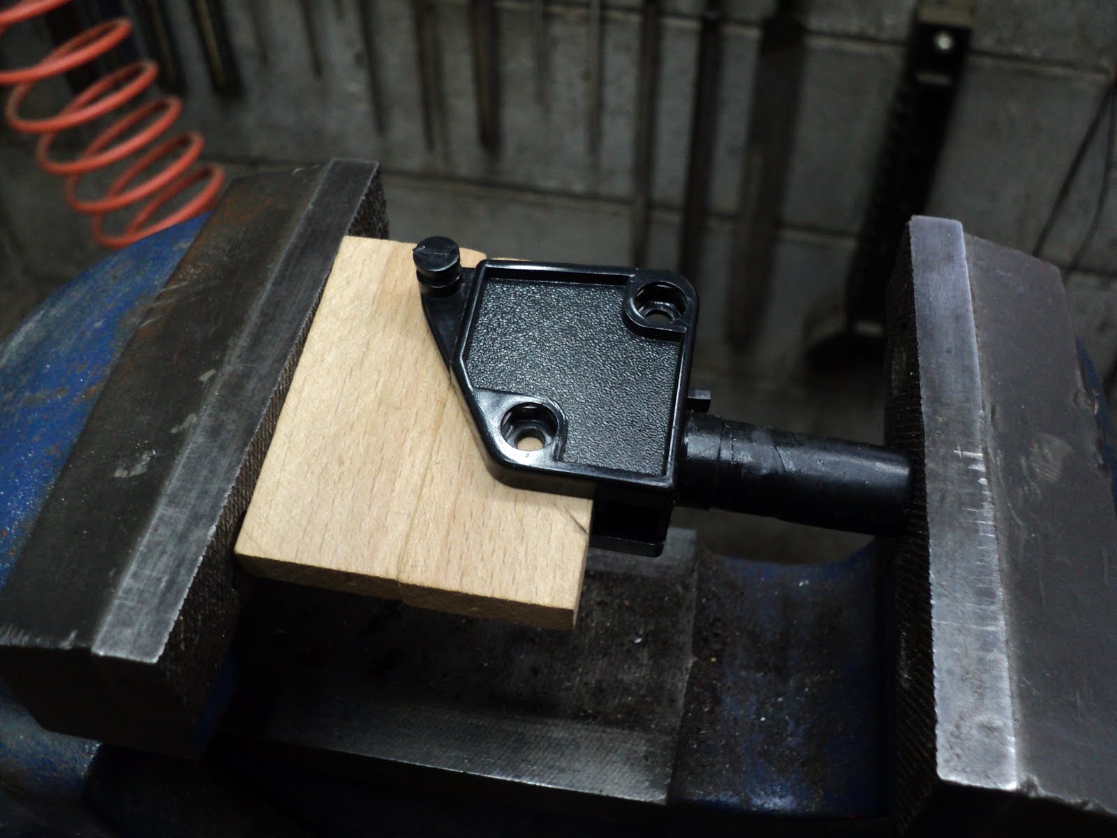
If you've ever wondered what's inside a barbeque burner valve, wonder no more. Here's one taken apart. (It's for a side burner on a low-end Thermos model.)

The conical valving element in the centre of the photo is the key to the valve's smooth, quarter-turn operation. When turned 1/4 turn CCW from its 'off' position, the hole in the side is fully aligned with a hole in the valve seat that exits to the jet. In the 'off' position, the hole is completely covered by the wall of the valve seat. In between is everything in between, from a low flame to fully on. It's about as simple, reliable and durable a piece of gear as can be.

Another key element is the dark grease you can see on the brass 'cone'. The grease acts as both a lubricant for smooth operation, and as a sealant. (We're dealing with very low pressure here -- about 1/2 PSIG[1]. Layers of o-rings are not called for.)

I looked into 'gas valve grease' on the internet, and such a thing can be had. When I went to the local appliance parts place and asked about it, they'd never heard of it. That makes me suspect that a lot of these things get discarded and replaced because of stiff operation, when they could easily be restored to perfect condition at little cost.

Since I can't easily get the 'proper' grease, I'll use MOLYSLIP on it after I've cleaned it up; it's the right colour, at least. (By the way, I know of no other field than lubricants, grease lubricants especially, that's so loaded with 'secret' formulae and miscellaneous techno-bushwah. Try and educate yourself about grease lubricants and see how much progress you make.)

All that said, in actual fact these valves probably very seldom need to be dismantled. Stiff operation, especially on a barbeque that stays outside, is likely to originate in the stem that the knob attaches to. WD-40 will deal with that without dismantlement.

The little spring in the photo does two things -- it keeps a seatward bias on the valving element, and it forces the stem up into its detent at the off position.

The jet is just an orifice. It was installed here with a hardening sealant. I'll use Permatex Ultra Grey on it when I reinstall it. (Teflon tape is for tapered threads only. These threads are straight.)

Finally, note the barbed hose nipple. (It takes 5/16" I.D. tubing.) Do you see anything magical or 'special' about it? I don't. And that brings me to the subject of barbeque hose replacement.

Barbeque Hoses

I hadn't owned my Thermos barbeque very long before a raccoon chewed the hoses. (It must have been an adolescent one still learning its way around in the world, discovering what all could be eaten. I guess I should be pleased that I was able to provide it with some education.)

The hose installation looked pretty straightforward to me, but embossed on the regulator was this: "REG-HOSE UNIT IS FACTORY SEALED DO NOT REPLACE HOSE ONLY"

Oh my, the voice of authority telling me that the raccoon had rendered a perfectly good regulator and two valve assemblies worthless. I wasn't buying it.

I went to Canadian Tire, and for $2.10/foot bought three feet of 5/16" I.D., 50 PSI fuel/emission tubing. It fit the barbed nipples perfectly, and has served me well for over six years now. Following is a photo of the two types of hose:

Above is the original hose; below is the replacement. They're both 5/16" I.D. They have about the same wall thickness. The original hose is slightly stiffer.

From what I've seen of barbeque fuel-delivery components, they're both durable and serviceable. I've never seen a failure of a sealed regulator unit, which is not to say that they never fail, but a salvaged working one could be used for a replacement if it ever came to it.

- - -

1. PSIG stands for Pounds-force per Square Inch Gauge, as opposed to PSIA -- Pounds-force per Square Inch Absolute. When you're measuring a tire pressure, you're reading PSIG; i.e. pressure relative to atmospheric pressure.

At sea level, a column of air one inch square the full height of earth's atmosphere weighs about 14.7 pounds. Everywhere on the face of the earth, the atmosphere is pressing on everything with about that amount of force. (It's less the higher up you are, obviously. At the top of a tall mountain, there's not so far to go to the top of the atmosphere.)

So a 35 PSIG tire pressure at sea level would be 49.7 PSIA -- the tire is inflated relative to its immersion in a surrounding atmospheric pressure of 14.7 PSI.

PSIG is almost always expressed as just 'PSI', as you can see done on the FUEL/EMISSION hose in the photo.

- - -


WEDNESDAY, JANUARY 12, 2011

Addendum

The main burner valves are little different in construction, but they feature some enhanced functionality. They have three detented positions, and a greater arc of rotation -- about 210 degrees, compared to 90 degrees for the side burner valve.

The first detent is the 'off' position.

About 80 degrees CCW from there is the 'light' position detent where the valve is fully open.

About 125 degrees CCW from 'off' is the 'HI' position detent. That appears to be a slightly throttled back 'fully open'.

At the end of CCW rotation is a 'low' setting. Here, the valve cone's side opening that's been in play for the 'light' and 'HI' settings is closed off, and a second, much smaller opening provides the path out to the jet. So, you have a fixed 'low' setting. I imagine the idea is to provide a reliable low setting that needn't be fiddled with to arrive at.

These valves are exquisite machinings that look like they can and should last forever.


# # #


# # #

Saturday, January 1, 2011

Piece of Crap

Pardon my language, but I'm a great believer in strict adherence to correct technical terminology, and a 'piece of crap' is what this thing is.

Pictured is the swivel base of an articulated magnifier lamp. I tugged the lamp toward me a little too forcefully yesterday and SNAP, the post broke off.

This is not the first time I've had to repair one of these things, but this one might be easier than previous ones because of the way that post was made. Those two holes go well up into the base portion, and I can exploit that feature to very good effect here.

Fortunately, the break is a clean one where the pieces mate perfectly when pressed together. That makes it much easier to get a good result. I can glue the post back on with CA adhesive, then come up with two steel rods of the right diameter to occupy those two holes. I'll install them with epoxy fill and I should have a sound repair.

- - -

It turns out that 3" common nails are about the right diameter; I just had to enlarge the holes a bit with a 5/32" drill, and the nails fit nicely. Two 1 1/2" lengths without points will do the job. Here's a photo, with one rod in place.


And finally, here it is with both rods and the epoxy fill.

I used five-minute epoxy, but I'll leave it to cure overnight before putting the part back in service. There's no hurry for it, and it's always best to let an epoxy repair cure fully before loading it.

- - -


And here it is back on the job. That should last approximately forever, give or take a day.

For a previous repair to one of these, I had to fabricate a new post from 1/2" diameter steel rod. (The broken-off post was either missing altogether or unusable for some reason.) 1/2" diameter was slightly undersize of the original post, and consequently ill-fitting in its socket. I got around that by making a wooden mounting socket for it with a 1/2" diameter hole bored in it.

If it ever comes to that again, I have a lathe now and I can turn an oversize steel rod down to the correct diameter.

- - -

SATURDAY, APRIL 30, 2011

Addendum -- Another One Bites the Dust

A lamp at my workplace with the identical type of swivel base has broken as well.

This one broke quite a bit lower down on the post, so I can repair this one with a single 'dowel', instead of the two rods that I used for the previous one.

That broken post's inside diameter is just shy of 3/8". I have some 3/8"-16 threaded rod whose thread crests are quite flat. Consequently, it's well undersize of 3/8". Consequently, it fits the post's bore just fine and will make ideal material for a dowel. The post's bore begins to taper inward at opposite sides part way up its length, so some filing to get the dowel to fit will be in order.

- - -

Here are the dowel and the upper part of the base ready for assembly.

Note the scores that I made with a Dremel burr on the inside of the upper part of the bore. The plastic there was very smooth and glossy -- unlikely to bond well with epoxy. The scoring will provide sufficient 'tooth' for the epoxy to get a grip on.

This post didn't snap off as cleanly as the previous one did, so it gave me a bit of difficulty as I was doing the initial glue-up with CA adhesive. I managed to get it together well enough, though. I used slow-curing epoxy here so I'd be sure not to run out of assembly time. Here's the finished part after curing overnight, and a bit of filing to correct the imperfect CA adhesive glue-up.

And here it is back on the job.

If you have one of these lamps, you might want to fit its base post with a reinforcement rod or rods and epoxy fill as a preventative against breakage. The swivel base posts on these things appear to all be doomed to fail.

* * *

Whoops! -- THURSDAY, NOVEMBER 1, 2012

Well, that repair lasted a year-and-a-half, until someone snapped the base post again. Here's a view of the damage.


I'll have to bore 3/16"[1] all the way through the post and the lamp base. Then I can fasten the two pieces back together with a 10-32 screw and nut.

- - -

I've bored through the length of the post, applied CA adhesive and clamped the thing togrther in the vise, like so.


I'll leave that to cure overnight. If the parts bond together well enough, I'll be able to complete the bore using the bored post as a drill guide.

- - -

Here's the glued-together lamp base set up in the drill press vise to be bored fully through.


And that worked fine. I got it bored through and the glue join is still intact.


A 2" screw plus a split lock washer and a hex nut finish it off.


- - -

Note:

[1] 3/16" (0.1875") is usually, but not always, clearance diameter for a No. 10 screw. The specs for No. 10 screws permit a major diameter as great as 0.190", so in some cases a 3/16" drill won't give you a clearance diameter hole. In this instance here, 3/16" worked ok.

# # #


# # #