Monday, February 25, 2013

Gloss Spray Paint Shelf Life


You'd think that something as well sealed up in its container as unused gloss spray paint would have an indefinite shelf life. That's what I thought, but nothing's ever as straightforward or simple as one might think.

I have quite a collection of spray paint cans. Some of them were bought for long-ago small paint jobs, then the cans got set aside on the spray paints shelf, sometimes for several years before being used again. When finally used again, the paints fail to deliver a 'gloss' finish. Here's an example:


[The pictured example is from this post.]

The paint is still 'good' insofar as it still sprays/colours/coats/protects the object painted, but it's not glossy -- it's more like semi-gloss or matte.

For whatever that's worth (and I know it's not worth much) be aware that an old can of gloss spray paint may not deliver glossiness.

# # #

FEEDBACK

# # #

Sunday, February 24, 2013

How I See Things


Ok, so what's this?


It's a slightly rusty, slightly bent steel tent peg with a blunt pointy end, obviously. What's not so obvious is what I see, near-instantaneously, when I look at it. What I see is this.


Here's how you get from one to the other. First, you hammer out the bentness on the back of the vise with a suitable hammer.


Then you clean the thing up by wire-brushing and steel-wooling and what-have-you.


Then you improve the pointy end a bit on the grinder, and touch up little dings and rough spots with a file.

You rig a way to suspend the thing for spray painting, clean it with lacquer thinner, and give it a coat of primer.


Then two coats of enamel.


And you have a tent peg that you're unlikely to leave behind at the campsite because you lost sight of it on the ground.

 # # #


 # # #

Saturday, February 23, 2013

Frying Pan Handle Revisited


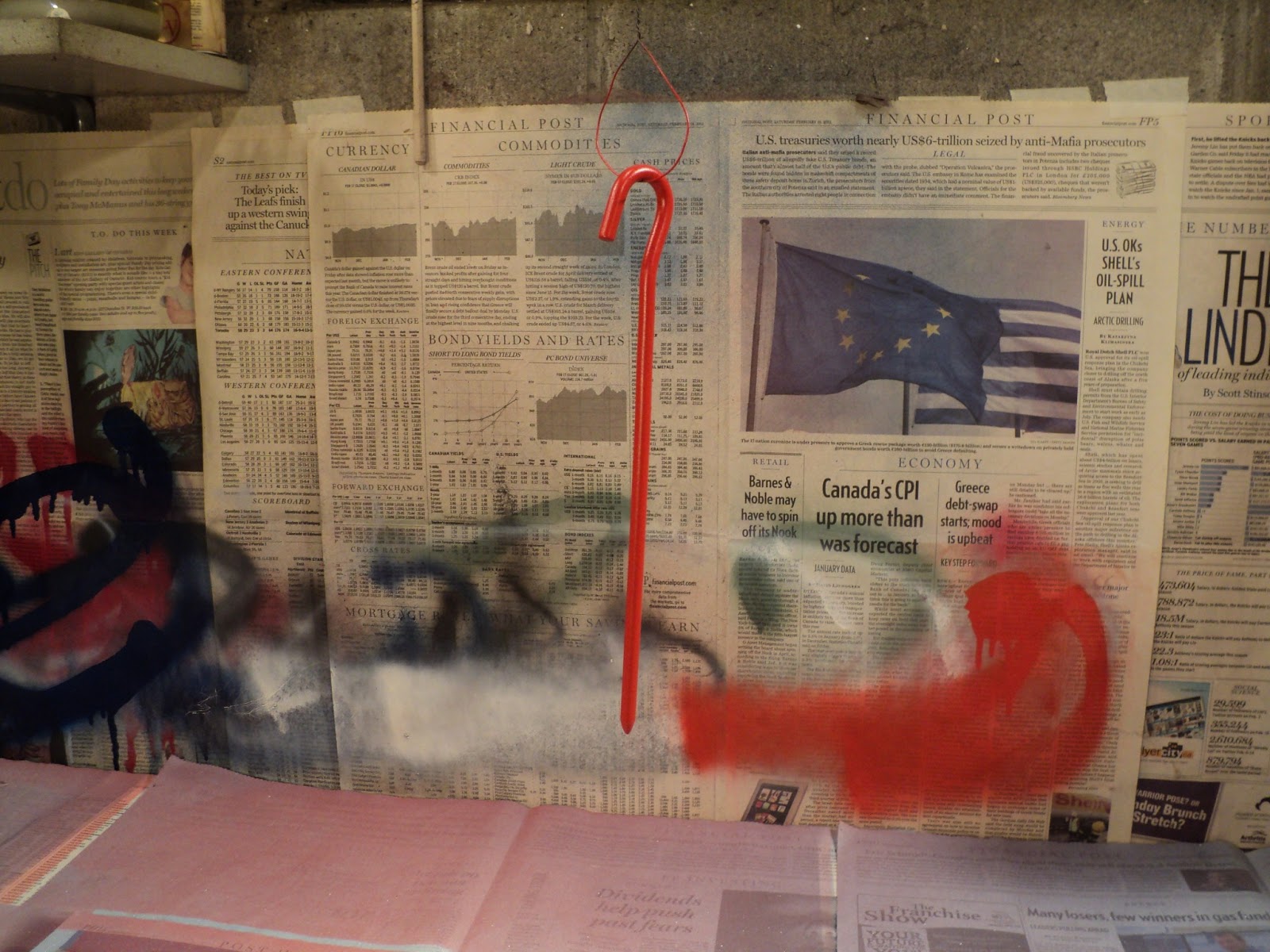
This frying pan handle couldn't take the heat.


The back story to this is here. I still like the method I used to construct that handle, but it's evidently not suited for application to a frying pan handle; the wood/metal interface is too compact, so the wood is constantly getting charred. The outcome pictured above was inevitable.

I'm going to salvage that wooden handle, but I'll reconstruct it in a different manner. I'll do it in much the same fashion as I made this saucepan handle. The saucepan handle's construction is far superior because the wood/metal interface is relatively large -- more heat will go into the handle, away from the very end of the handle where it attaches to the frying pan. Here's a view of the components I'll be putting together.


The machined brass hose fitting is for 1/2" I.D. hose; the threaded rod is 1/2"-13 x 3" long. I don't have anything suitable on hand to make a ferrule from, so I'll use that 22mm hose clamp for a 'ferrule'. It won't be pretty, but it will do the job.

The hose fitting's bore is just shy of 1/2", so I'll run a tap through it to produce a vestigial female thread for the threaded rod. Here's a view of that operation just completed.


So now, I have the makings of a substantial, heat-sinking wood/metal interface, like so.


Next up is to bore the handle to accept the threaded rod and hose fitting assembly. There'll be four steps to that:

1) Centre drill to establish an initial, shallow pilot hole.

2) Drill a 3/16" pilot hole for the 5/8" spade bit that will bore the clearance for the hose fitting's barbed shank.

3) Drill 5/8" deep enough for the hose fitting.

4) Drill 1/2" deep enough for the threaded rod.

Here's the first step done.


That, and the follow-up 3/16" pilot hole was easy. For the 5/8" bore, I put a hose clamp on the work for reinforcement. Here's the 5/8" bore completed.


And here's the 1/2" bore completed.


And it all fits together.


Now I just have to clean everything, mix up a batch of J-B Weld epoxy and do the final, epoxy-bedded assembly.

- - -

Whoops!

As I was squeezing together the epoxy-slathered components in the vise, I was a little too quick and forceful, and I got a demonstration of hydraulic force at work, like so.


The wood cracked open and left me with a streak of squeeze-out where it wasn't supposed to occur. Fortunately, no real harm has been done there. I'll trim off that squeeze-out, and the flaw will be all but imperceptible. The crack is sealed against water incursion, and it's not extensive enough to be a structural defect.

What I should have done there as I was squeezing the handle parts together was do it very slowly, so the excess epoxy could all escape past the hose fitting in its own sweet time. J-B Weld mixes up into a very thick paste. I tried to rush the stuff, and it won't be rushed. Anyway, lesson learned. (For what it's worth, following is a close-up of the crack after trimming and sanding.)


- - -

A Ferrule

The saucepan handle has been serving as the frying pan's handle for several months now, and it's holding up fine. That handle has a true, encircling ferrule at its end where it attaches to the pan, and it occurs to me that that ferrule may be a key component -- it acts as a 'front line' heat dissipator for the wood. This handle is past the point where I could fit it with a ferrule in exactly the same way, but I can fake it with a split ring of copper pipe; it should at least be better than nothing.

- - -

Here's what I came up with.


That's a 3/4" length of 3/4" thin-walled (Type M) copper pipe. That 22mm hose clamp just manages full worm engagement over the final diameter.

I'll do a final assembly with a smear of J-B Weld under the copper 'ferrule', and I should have a handle that can take the heat. We'll see.

- - -

A Fresh Coat of Tung Oil -- MONDAY, FEBRUARY 25, 2013

Yesterday, I gave the wood a fresh coat of tung oil. I quite like the results I get from tung oil. Here's a view of the handle to date.


The photograph scarcely does the handle justice. The oil finish has a soft clarity to it that enhances the delicate figuring of the hardwood grain beneath. What the photograph can't show is the feel of the thing -- it's smooth but not slippery -- it's exquisite. As frying pan handles go, this is as pretty as they get.

Come the weekend, I'll re-install this handle on the frying pan, and commence observing how well and how long it stands up to its task.

- - -

Finally -- SUNDAY, MARCH 10, 2013


There it is re-installed and ready to go. We'll see if this reconstructed handle can take the heat.

Hose fitting threads are a pretty loose fit, so I wrapped eight turns of Teflon tape around the male thread, with the tape overlapping the end of the fitting so it would double as a gasket at the end of the fitting. The head of the hose clamp gave me a nice purchase-point for tightening the thing with Channellocks, without marring the handle at all.

The radial position of the hose clamp's head just happened to turn out as I wanted it -- the head facing down so it's pretty much out of sight. Had it not turned out that way, I could easily have made it so by adjusting the fastening of the female fitting.

That downward sloping attachment of the handle looks a bit odd, but on the stove it's not at all a problem. If anything, it's actually a bit of a safety improvement on the orthodox configuration -- the handle isn't sticking up where it's easily struck inadvertently.

- - -

Update -- FRIDAY, DECEMBER 19, 2014

The revised handle described above has lasted the better part of two years now, but it's looking a bit shabby.


So, I've made a new, more substantial one.


This time, I knew to provide a vent hole for the J-B Weld epoxy to escape from as I pressed the handle's components together. A tiny hole is all that's needed. I used a No. 60 (0.040") drill. After sanding and finishing the handle, the only evidence of the vent hole is a tiny, grey dot, like so.


I've given the handle a single coat of tung oil for a finish. The larger diameter of this handle (1 3/32") feels much better in the hand than the old, 7/8" diameter handle did. We'll see how it holds up.

# # #


# # #

A Frying Pan Handle

SUNDAY, OCTOBER 31, 2010

This is a companion piece to an addendum to "Somewhere, a Saucepan Needs a Handle". It picks up where the addendum leaves off.

This did not go as smoothly as I'd thought it would. I got caught out by some wood behaviour that I didn't foresee. I tell about that following the subtitle, "Whoops!", much further down.

Ultimately, this method of constructing a frying pan handle proved to be a failure. However, the matter of mating a piece of hardwood to a metal fitting by way of an interference fit remains of interest to me, and may prove useful some day in some application.

I salvaged the wooden part of the failed handle, and reconstructed it in much the same manner as I made the saucepan handle. We'll see how it holds up.

* * *
SATURDAY, OCTOBER 9, 2010

I don't like to leave loose ends unattended to, so I'll make the frying pan a new handle, and return the saucepan's handle to the saucepan. The hose fitting pictured below has given me an idea for a handle construction method quite different from that used to make the saucepan handle.

As with just about everything, there are endless variations of hose fitting construction. This one's nipple/ferrule is entirely made of light gauge pressed metal, inserted into a cast/machined threaded fitting and swaged in place.

I'll chuck it in the lathe and cut away the lip at the end. Then I should be able to extract the nipple/ferrule. What I have in mind is to make a handle with just that cast metal piece press-fitted onto the handle's end. It'll be a one-piece handle-reinforcement ferrule and threaded fitting.

- - -

That separation exercise worked out remarkably well; I've got my threaded fitting. It's bore is roughly eight thou greater than 3/4".


That bore dimension and how I arrived at it raises an issue of measurement methodology deserving of its own post. Here it is. I also explain there how I obtain the press-fit dimension for this handle.

The Wooden Handle

I have more of the same broomstick material that I used for the saucepan handle. I'll use it for this handle, but I'll make this one just a plain cylinder with no contour to it, so as to lose as little diameter as possible. I want this handle to be a bit more substantial.

Here's the new handle with its fitting:

I've turned that land at the end of the handle to a diameter that will be a press-fit in the hose-fitting's bore. The length of the land is just less than the length of the bore, so that I can be certain of getting the handle pressed in all the way to the shoulder of the land.

Note the three grooves on the handle's land, and in the bore of the fitting. The grooves are positioned so they'll align with one another when the two pieces are joined together. Just prior to assembly, I'll smear the land and the bore with J-B Weld epoxy. Once cured, the epoxy-filled grooves will effectively act as embedded lock-rings, securing the assembly from ever working apart.

Here's the assembly in the press, having just been pressed together.


(Something about that wooden cylinder gives my camera fits. I cannot get it to photograph well.)

While I was setting this up, I attached a disc of glossy cardstock to the end of the press' ram with carpet tape, so the ram wouldn't mar the end of the handle. Now I just have to clean up the squeeze-out, and I can leave it for the J-B Weld to cure overnight.

- - -

Here's the outcome. Not too shabby, if I do say so myself.


All that's left is to bore a shallow hole in the fitting end of the handle, to clear the screw head inside the cap that's attached to the pan. Then I'll give the handle a coat of tung oil and let that harden.

I'll post a photograph of the whole thing installed on the frying pan when it's all done.

- - -

And here's the pan with its new handle back home on the range. (Sorry! Couldn't resist.)

In closing, here are a couple of lessons learned along the way:

a) When I had the saucepan's handle on this large diameter pan, the pan wouldn't sit flat in the sink for scrubbing because of the handle's length. This new handle is short enough for the pan to fit properly in the sink; a consideration that's easily overlooked when fabricating a handle.

b) The idea of having an easily removed handle as an aid to washing up didn't pan out, so to speak. Unless the handle is removed every time the pan gets wet, water will seep into the fitting and stay there. Also, an easily loosened handle could be a safety hazard at times.

I installed this handle with the threads smeared with Permatex Ultra Grey silicone gasket maker. It remains to be seen how that material stands up to the heat. I'll update this post if I find that heat resistance is an issue for either the Ultra Grey or the red threadlocker.

- - -

SUNDAY, OCTOBER 10, 2010

Whoops!

My press fit loosened up after this morning's use of the pan. The J-B Weld 'lock-rings' are keeping it from coming apart, but it's loose in the threaded fitting.

I unscrewed the handle from the pan and examined it. The heat shrank the hardwood handle considerably. I wasn't expecting that from such well-seasoned wood. Evidently, I was asking too much of my press fitted assembly for the temperatures it's subjected to in use, and the approach I took with the saucepan handle is the superior one.

But I'm not defeated yet. I'll apply CA adhesive so it can wick in and fill the shrinkage void, and pin the thing through with a 3/32" x 1" roll pin.

- - -

Here it is with the roll pin installed:

This time I'll wrap the threads with teflon tape before screwing the handle back in. I'd rather not have to deal with the silicone gasket maker should I have to take this apart again.

- - -

SUNDAY, OCTOBER 31, 2010

Update

The pan's been in use for two weeks now, and the handle still appears to be sound. Needless to say, I'll stick with the saucepan handle's construction method should I ever need to make another pan handle.

The heat-induced failure aside, I'm still quite pleased with how that press-fitting turned out. That could still prove to be a useful technique somewhere that's not subjected to high temperatures.

- - -

SUNDAY, JANUARY 2, 2011

Update

The handle attachment point of a frying pan is a hotter place than I expected it to be. After two full months of regular use, the end of my press-fitted wooden handle is showing signs of charring.

It's loosened somewhat again. The roll pin may be all that's really holding it in place by now. I'll reapply CA adhesive and reinstall it. It will be interesting to see if this effect ever stabilizes, or if I'll ultimately have to make another handle by my other method.

MONDAY, JULY 11, 2011

Update

The handle was forever loosening and being retightened. Red loctite is not up to withstanding the temperature that a frying pan routinely gets up to. Ultimately, the welded-on boss on the side of the pan gave way and came off. The hose fitting cap that receives the handle is now bolted directly to the side of the pan. It looks a bit odd, to say the least, but it actually functions remarkably well this way. It's pictured below. (Also in the shot is what's left of the boss that came off.)

The burner grates on our gas stove are fairly high, so the pan sits up high enough that the downward-sloping handle is not at all a bother.

Further to the charring that I was getting, the charring effect kept on keeping on and loosening the handle end in its threaded collar. (And I've since learned that CA adhesive is not terribly heat resistant.) I drove out the pin and removed the collar, cleaned everything up and smeared JB Weld on the interface before reassembling and repinning it. That seems to be holding up.

The inner wall of the pan now has a screw head in it, like so.

That's really not at all a bother, either. Attaching the hose fitting cap this way, with a screw and a nut, makes it possible to really tighten the cap in place -- it hasn't been coming loose since I attached it this way.

So, I may finally have a durable handle here.

If nothing else, this exercise points up something to consider when shopping for cooking pans; i.e. handles attached by a single screw are prone to become troublesome with age -- they're pretty much doomed to fail eventually. Handles attached with rivets will no doubt far outlast handles attached with a single screw. Here's an upside down photo of a good example.


Now that's a handle attachment that will no doubt last forever.

- - -

SUNDAY, FEBRUARY 26, 2012

Whoops II!

A few weeks ago, the handle snapped off right at the ferrule. Here's a view of the ruin.

I've replaced it with the saucepan handle for now.

It lasted for over a year, which is a bit shy of forever, which is how long I like things to last. A rethink is in order, evidently. I'd still like to find a way to make this handle construction last, but I may have to make another handle patterned after the saucepan handle.

# # #

FEEDBACK

# # #

Friday, February 15, 2013

Fractional Inch Vernier Caliper

[SUNDAY, AUGUST 14, 2011: I've added a brief note on how a fractional vernier is read. Scroll way down.]

I bought the pictured caliper at Lee Valley in 2006 for $21.50, and it's a wonder I haven't worn it out; I use it very frequently. (The caliper is still available -- the catalogue number is 88N70.01.)

Note that the inch scale is fractional, not decimal. That's what makes the thing so useful to me. A precision caliper that reads directly in fractions of an inch along with millimetres is a real blessing in the workshop. (And I don't mean to appear backward or unschooled here. I'm quite conversant with metric and decimal inch measure as well, and I make use of them both as it suits me to.)

It actually baffles me a bit that precision fractional inch vernier calipers have always been a somewhat obscure item, considering the ubiquity of fractional inch measure that still adheres throughout Canada and the USA.

Anyway, I wanted to introduce the tool and recommend it. If you're a boomer of a certain age for whom fractional inch measure is second nature, I think you may find it useful; I certainly have. And if you're beginning to think I'm some kind of shill for Lee Valley, read on. I'll tell you of the problem I encountered with this caliper, and how I solved it.


- - -

If you look closely at the caliper's inch cursor in the photograph, you'll notice that the screw recesses have a rather blank appearance, unlike those in the metric cursor, which obviously contain tiny screw heads. There's a reason for that; the inch cursor has no screws holding it in place.

When I got the caliper home and started using it, I noticed that the inch cursor was imperfectly zeroed. Rather than go through the aggravation of returning it to the store, I set about looking into what could be done to zero it.

I loosened the cursor and tried to zero it and retighten it -- no way. If anything, I'd made it worse. What no doubt happened at the factory was that the assembler encountered a marginal cursor fit, levered the thing into place as best he could with whatever means he had at his disposal, said, "Close enough for this outfit." and boxed the caliper. I doubt he'd have been thanked for doing otherwise.

Since I could see no way to zero the cursor and install the screws, I tried a different approach. I thoroughly degreased the cursor mounting area with lacquer thinner, got the cursor in place and zeroed, clamped it there and then filled the screw holes with epoxy. It worked remarkably well. The feel of the slide on the beam is flawless, and it's held together for four years now.

So there we are. When a twenty-buck 'precision' tool comes up a bit short on precision, there may be a way to deal with it. There certainly was in this case.

By the way, there's more to fractional inch measure with this caliper than meets the eye. See this post for a look at a practical application of some really tiny fractions of an inch.


- - -

SUNDAY, AUGUST 14, 2011

Addendum -- Reading a Fractional Vernier

It dawned on me recently that some may have found this post while looking for instruction on how to read a fractional vernier. I'm not a mathematician, and I'm not going to attempt a rigourous explanation, but following is how I understand it. It works for me.

If you enlarge the above photograph, you can clearly see that the caliper is reading zero -- the cursor's zero is directly aligned with the beam's zero. Now, look at where that puts the cursor's '8' -- directly aligned with the beam's '15/16'. So, we can think of the cursor as representing a 'short inch' that's 1/16" shy of a full inch.

That 'short inch' on the cursor is divided into eight equal parts ('short eighths'). Each of those 'short eighths' is 1/128" shy of a full eighth. (True. You're more than welcome to work it out and prove it.) So, moving the cursor rightward until the cursor's first 'short eighth' aligns with the beam's first full eighth represents a cursor displacement of 1/128". As each successive 'short eighth' aligns with each successive full eighth, another 1/128" of cursor displacement occurs until we arrive at a direct reading of 1/16".

Here's the sequence of eight 'short eighth'/full eighth alignments that occur within 1/16" of cursor motion to the right:

1/128"

1/64"

3/128"

1/32"

5/128"

3/64"

7/128"

1/16"

Think of it this way; what the cursor's divisions do for you is they give you a means of accurately interpolating eighths of sixteenths. One-eighth of one-sixteenth is 1/128th.

And that's the best I can do. I'd be delighted to read a better explanation if anyone has one.

And by the way, the vernier scale was invented by Pierre Vernier. He published the invention at Brussels in 1631. How's that for leaving a legacy?


- - -

MONDAY, AUGUST 15, 2011

Addendum No. 2 -- A Fractional Vernier Variant

As with everything, there's a variation on the preceding. Pictured below are a couple of examples of half-inch/'short half-inch' verniers.

The nominal resolution is the same at 1/128", but the eight-division vernier on the cursor is only 7/16" long. On these verniers, one is looking for successive 1/16" alignments, rather than successive 1/8" alignments. Apart from that, the operating principle is no different.

Obviously, though, the inch/'short inch' vernier has inherently better visual resolution owing to its increments being more spread out.


# # #

FEEDBACK

# # #

Saturday, February 9, 2013

Tubing As A Repair Material


Tubing, of all types, materials and sizes, is one of the most useful, versatile repair materials on earth. I salvage the stuff at every opportunity, and stash it in bins sorted by external diameter. Countless times I come up with neat repair methods by looking in on my supply of tubing. Here's a small, but telling, example of the sort of thing salvaged tubing can do for you.


That broken plastic clothes hanger is no heirloom, but it can still be made serviceable -- there's no need to add it to the landfill.

That bit of tubing in the photograph is the key to a strong, simple repair here. It's butt-seam tubing, about 10mm O.D. x 8mm I.D. x 45 mm long. I just have to trim some mould flash off the hanger where the tubing is to go, and the tubing will fit over the broken ends of the plastic just fine.

Here's the tubing installed.


I'll apply CA adhesive at the tubing's ends, and along its seam, and let it wick in. That will give me a repair that should last approximately forever.

# # #


# # #

Sunday, February 3, 2013

A Snap-Fit Plastic Hinge Repair


[When I began this, I was not at all certain that I could pull it off, but it turned out remarkably well.]

I have a very fine tire pressure gauge with a plastic case. The gauge is superb; the case leaves a bit to be desired. Here's a view of the two 'halves' of the case.


The problem is with the black portion of the upper hinge half. That's the 'female' portion of the hinge, and its socket wall is chipped and won't retain the 'pin' of the clear half of the hinge. It doesn't photograph well, but here's a close-up.


Those hinge halves are about 5/32" 'diameter' -- substantial enough to be drilled through 1/16" diameter for a pin. Drill 'reach' with a standard 1/16" twist drill is likely to be marginal on the black portion, and setting up the pieces on the drill press with acceptable axial alignment with the drill may be challenging.

The drill reach problem, fortunately, is something I solved quite some time ago with this technique. By lengthening a standard drill's shank with brass tubing, I'll have no trouble with reach. As for axial alignment, all I can do is do the best job I can of aligning the work to the drill by eye, and hope for the best. Here's the black portion's hinge half successfully drilled through.


(In the above photo you can see very clearly where the hinge socket is chipped.)

The clear portion's hinge half was rounded on top. I had to file that flat so I could dimple it with an awl for a reliable start to the drilling. That worked out ok -- here's the clear portion's hinge half successfully drilled through.


Both drilling operations went well; here's the hinge assembled with a length of 1/16" rod trial-fitted as a hinge pin.


It dawned on me at this point that a cotter pin would make an ideal hinge pin. Here's a 1/16" x 1" cotter pin installed.


Not a bad outcome at all.

That clear lid is begging for a paint job -- it's pretty shabby looking, and I don't need to be able to see through it to know what's inside.

- - -

I had grey primer, and a bit of leftover metallic silver enamel on hand. Here's the lid with the second coat of enamel just applied and still wet.


When that paint has hardened and I have this all done, I'll photograph it again along with the gauge that resides in it.

* * *

All Done -- FRIDAY, FEBRUARY 8, 2013

Here's the case reassembled with its painted lid.


(Some blemishes on the clear plastic 'telegraphed' through the paint. I don't know if there's a sure way to preclude that from happening -- sanding, possibly.)

And here's the gauge back in its renovated home.


Update -- SATURDAY, AUGUST 20, 2016

The lower hinge developed exactly the same fault that the upper hinge had, and I repaired that in exactly the same way. Here's a view of the case now that both hinges are pinned with cotter pins.


Having to repair both hinges in this manner introduces a slight complication -- both hinges' pin-bores ought to share the same axis, and that's a difficult condition to meet.

I've managed to get close enough that the repair does work, but there's a slight binding condition when the cover is fully opened. That binding is an indication that the two hinges' axes are not perfectly in line with one another.

As long as the hinge bodies can tolerate the stress that the slight misalignment introduces, the repair will continue to function ok. If the stress should result in a cracked hinge body, then it will be game over for this plastic case. We'll see if this repair lasts.

# # #

FEEDBACK

# # #