Monday, October 19, 2015

Ryobi RY09466 Leaf Blower -- Engine Teardown


See this post for the externalities tear down to get the engine out of the machine.

Here's a view of the engine.


I'm only tearing down this engine for amusement. No internal parts are available for it -- an overhaul is not on. I'm just curious about how it looks inside; it has almost no compression, and won't sustain operation at wide open throttle.

So, here goes a step-by-step tear down, for what it's worth.

1) Drain The Oil

2) Air Cleaner Body


- Crankcase ventilation tube off of nipple at top of air cleaner body.

- Primer suction tube off of nipple at right side of carburetor.

- Two M5 prevailing torque hex nuts (8mm A/F).

3) Carburetor & Gasket


They're free to just come off.

4) Breather Check Valves & Tubing


Note the directionality of the two check valves. Each valve's conical end points in the direction of flow.

5) Carburetor Heat Dam, Baffle & Gasket


Two M5x22mm washerhead screws (T25 Torx recess).

The screws were installed with threadlocker, and will take some effort to remove.

The gasket will likely be firmly stuck to the cylinder head.

6) Muffler & Gasket/Heat-Shield


Three M5x38mm truss head screws w/split lockwashers (T25 Torx recess).

7) Spark Plug


It's a Champion RY4C -- 5/8" A/F; 0.025" gap.

8) Ignition Module


I don't have a gap figure for it. It measures about 0.008".

9) Flywheel


A 3", two-jaw puller gets it off nicely.

10) Valve Train Cover & Gasket


One M4x27mm washerhead screw (T20 Torx recess).

11) Crankcase Cover


Nine M4x12mm cap screws (T20 Torx recess).

- - -

And here we have an engine that's well and truly done like dinner.


It's impossible to photograph well, but the cylinder wall scoring is horrific -- you can feel the ridges.

This engine must have been run out of oil. It's a wonder it was still able to run at all.

Conclusion

These little engines demand reasonably conscientious attention. A 65ml sump capacity leaves very little margin for neglect.

This particular engine came to an unfortunate end, but that's no reflection on the engine's quality of manufacture. These machines are jewels of precision engineering and construction, and ought to be treated accordingly.

# # #


# # #

Ryobi RY09466 Leaf Blower Tear Down


I have an old Ryobi RY09466 leaf blower with an utterly worn out engine. It was a $2.00 garage sale find that didn't pan out, so it's pretty much landfill. (See this post for the back story, and some basic maintenance information.)

I've got plenty of time, and little else better to do, so I thought I'd tear the machine right down, and at least get a good look at its cylinder wall, to see what the damage looks like. Overhauling the engine is out of the question -- the parts, if I could even get them, would likely cost me at least as much as a new machine. But if I can learn more about small engine architecture, I'll be happy. So, here goes.

Here's a view of the complete machine as obtained.


Its external choke lever is broken off, and the air cleaner cover and filter element are missing. Judging by its very low compression, the machine has seen long service, and heaven only knows how long it was run without an air filter.

1) The Nozzle


Shown above is the nozzle in its latched position. The latching effect is very secure. I needed a big pair of Channellocks to twist the nozzle out of its latched position. Twist CCW (as viewed nozzle-output-end-on) to unlatch it from its studs, then pull it off.


2) The Right Side Engine Cover


Four No. 8 x 11/16" threading screws, and one M4 special shoulder screw (all T20 Torx recess).

3) Right Side Of Handle


Three No. 10 x 3/4" threading screws (T25 Torx recess). Watch out for a little steel rod part (a ground wire) at the top of the handle -- it will be free to fall out once you take away the right side of the handle.

4) Throttle Cable Disconnection


Throttle cable anchor removed from air cleaner body. (One M4x16mm pan head screw -- T20 Torx recess.) Throttle cable disconnected from throttle crank.

5) Kill Switch Disconnection


Two spade terminals.

6) Bottom Right 'Handle'


Two No. 10 x 1/2" truss head screws (T25 Torx recess).

7) Fuel Tank


[The above photo is in error -- the bottom right 'handle' shouldn't be there.]

Two fuel line connections:

- The front-most line connects to the lower carburetor nipple; that's the fuel supply tube.

- The rear-most line connects to the right side primer bulb nipple; that's the fuel return tube.

Three No. 10 x 3/4" pan head screws (T25 Torx recess).

8) Left Side Cover


Seven No. 10 x 3/4" pan head screws (T25 Torx recess); one latch.

9) Impeller


One 3/8" - 24 nylock hex nut (9/16" A/F). The nut is a right hand thread. Use an impact wrench to free it. NOTE the two oversize flat washers.

10) Impeller Housing W/Starter


Four M4x19mm cap screws in deep wells (T20 Torx recess). NOTE the sleeve and flat washer on the output shaft.

- - -

And there we have the engine free of its externalities.


I'll begin a new post for the engine tear down. This post is getting dangerously lengthy.

# # #


# # #

Sunday, October 18, 2015

Homelite 3514c Chain Saw -- Top Cover Removal


The top cover of the Homelite 3514c chain saw can be a bit obstinate, and the removal procedure given in the operator's manual is hogwash. Here's how to get the top cover off.

First, remove two No. 10 x 5/8" threading screws (T25 Torx recess). They're in deep wells at the rear corners of the cover.


The remaining hindrance to removal is a difficult-to-see hook & stud at the front left of the cover. Here's the best I can do to illustrate how that's dealt with.


You have to get a screwdriver into the sweet spot between the hook, and the left side of the cover. Twist/pry and the little stud on the cover will snap free of the hook, freeing the cover.

Here's a view of the hook & stud that make top cover removal difficult on this machine.


Getting the cover back on is not so easy, either. It tends to fight you at two places.

a) At the left front corner, in the vicinity of the hook & stud, there'll be an overlap that has to be forcefully overcome.


b) At the rear, by the primer bulb, there's a lip that may need to be coaxed into place.


And there we are. Put the two screws back in, and you're away.

# # #


# # #

Saturday, October 17, 2015

Poulan 2050 Chain Saw -- Carburetor Diaphragm Replacement


Hard starting, and failure to idle/accelerate, are symptoms of a stiffened carburetor metering diaphragm. Use of ethanol-laced gasoline makes diaphragm stiffening inevitable after a few years of service.

Following is the procedure for diaphragm replacement on a Poulan 2050 chain saw. (The carburetor shown here is a Walbro WT324.)

1) Top Cover Off


Loosen off three captive No. 10 screws (T25 Torx recess) to free the top cover. The cover comes away easily.


Note the pinched spark plug wire. Someone was careless once when reinstalling the top cover, and pinched the wire's insulation quite badly. Fortunately, the wire's conductor is undamaged, and the wire still functions.

2) Air Filter Element Removed


3) Air Filter Housing Removed

Two M5 flange nuts (8mm A/F).


That gets you to where the carburetor is unfastened. Note the following:

- Choke Pull

Don't try to free the blue choke pull from the choke lever plate. Just slip the choke pull's grommet out of its notch. The choke pull can remain attached to the carburetor throughout this job.

- Fuel Lines

There are two to be disconnected.

The upper one is fuel supply from the left side of the fuel tank.

The lower one is primer suction from the rearmost primer bulb nipple.

- Throttle Link

With the fuel lines disconnected, you can manipulate the carburetor so as to disconnect the throttle link.

4) The Carburetor Off The Engine


5) The Pump Side

A single 8-32 x 3/8" pan head screw fastens the pump cover in place.


Note that the diaphragm goes to the body of the carburetor; the gasket goes to the cover.

6) The Metering Side

Four 4-40 x 1/4" pan head screws fasten the metering diaphragm cover in place.


Note that the diaphragm goes to the cover; the gasket goes to the body of the carburetor.

Note also that there's a small extra hole in the cover aside from the screw holes. That hole must be clear of debris, and open to the atmosphere, in order for the metering diaphragm to function.

# # #


# # #

Chain Saw Carburetor Contamination


Here's a view of a sawdust-contaminated carburetor off a Poulan 2050 chain saw.


The saw had experienced a fuel line tubing failure, and probably ran for awhile with its fuel filter broken off from its fuel pickup tube.

I guess the lesson is, "Dismantle and flush any carburetor that's been run without a fuel filter."

# # #


# # #

Wednesday, October 14, 2015

Fuel Line Tubing Nipples For Small Engine Fuel Tanks


A common practice among manufacturers of small engines is 'squeeze-through' installation of fuel line tubing. Here's an example of it on a Ryobi leaf blower.


The fuel tank has no nipples. At the factory, the resilient fuel line tubing is squeezed through undersize holes in the wall of the fuel tank to effect a sealed installation.

It's a dirt-cheap method that lasts for at least the warranty period, so the manufacturers love it. Serviceability leaves something to be desired, though.

Fuel line tubing installations all have a finite life; eventually, the tubing gets brittle/rotten and fails. If you can get exact replacement tubing, you can probably re-create the factory's tubing installation. If available tubing is undersize or oversize in the outside diameter dimension, you have a problem.

I've taken to getting around the problem by fabricating nipples from 1/4" - 20 threaded rod, and 1/8" hard brass tubing. Here's a view of such an installation on a Weed Eater string trimmer's fuel tank.


It's a bit of work, and parts of it can be awkward (e.g. fitting the fuel pickup tube inside the tank), but it gives you a fully serviceable fuel line tubing installation that's not fussy about tubing outside diameter.

I have an old Poulan 2050 14" chain saw that's in need of new fuel line tubing. The machine's fuel tank architecture is not friendly to modification, so this will be a bit of a challenge. But it will let me use tubing that I have on hand, saving me a trip to the small engines place. Also, even if I had just the right tubing, it would be very difficult to re-create a squeeze-through tubing installation on the Poulan's fuel tank. It's not a design that lends itself to serviceability.

Before starting in on one of these jobs, make certain to create a photographic and/or written record of your machine's correct tubing connections -- they can be a difficult thing to puzzle out without documented guidance. A typical installation will have the following elements:

a) Fuel pickup tube from fuel filter inside tank, through tank wall, to fuel pump side of carburetor.

b) Primer suction tube from primer bulb to metering side of carburetor.

c) Primer return tube from primer bulb to a hole in the tank wall.

Items 'a)' and 'c)' above are those that need to get nipples provided.

Fuel Tank Preparation

Drill out the tank's tubing squeeze-through holes with a No. 7 drill, and tap the holes 1/4" - 20.

Here's a view of the upper wall of the Poulan's fuel tank with its two squeeze-through holes.


The smaller, upper, left-most hole is for fuel pickup. That will need a double-ended nipple.

The larger, lower, right-most hole is for primer return. A single-ended nipple will suffice there.

And here we are with the two holes drilled out and tapped, and all the chips blown away with compressed air.


The Nipples

Here are two finished nipples.


The 1/4" - 20 threaded rods are 13/32" long; the 1/8" O.D. tubes are 1" long. The threaded rods were bored through on a lathe. The pieces are assembled with CA adhesive. Note the filed wrench flats. (It was just as easy to make both nipples double-ended, even though only one of them needs to be.)

Coat the threads with CA adhesive prior to installation, and be ready to screw them fully in quickly, before the CA adhesive seizes on you. The fuel pickup nipple will have to have its tube in place before the nipple is installed -- it will be very difficult, if not impossible, to get the tubing on the end of the nipple, once the nipple is in the fuel tank.

With the fuel pickup nipple installed, attach the fuel filter from outside the tank, and tuck the works inside the tank.


And here's how the nipple installation looks up top.


Now it's just a matter of reinstalling the carburetor with correct tubing runs. If everything else about the engine is ok, your machine will be back in business. The subject chain saw here primed properly and started up easily with this repair/modification done.

# # #


# # #

Sunday, October 11, 2015

Ryobi Model No. RY09466 (Maybe) -- Garage Sale Find


Well, what have we here?


A $2.00 garage sale find that's missing its air cleaner. Hmmm.

There's no I.D. plate on it anywhere that I can find. I think it's a model No. RY09466. I found an operator's manual for that model on-line, and downloaded it and saved it.

This is a four-stroke cycle machine. I'll check the oil, and find the spark plug and check for spark.

Engine Oil

The sump is empty -- not a good sign, although the engine certainly isn't seized.

According to the operator's manual, the engine takes 65ml of 20W-50. I have sufficient SAE 30 on hand, which the manual also permits the use of. I won't fill the sump until I've confirmed that there's spark. If there's no spark, this thing is landfill.

Spark Plug Access/Spark Plug

Remove the right side cover to begin to gain access to the spark plug. You'll need a T20 Torx driver.

There are four No. 8 x 11/16" threading screws, and one M4 special shoulder screw that secure the cover. Remove the five screws to get to here.


The spark plug is a Champion RY4C. Gap is 0.025". Hex size is 5/8" A/F.

The plug is awkwardly situated toward the front of the engine, like so.


In order to get a socket wrench onto the spark plug, you have to remove the right side of the handle.

Remove three No. 10 x 3/4" threading screws (T25 Torx recess). Watch out for a little steel rod part (a ground wire) at the top of the handle -- it will be free to fall out once you take away the right side of the handle. Here's a view of the machine with the right side of the handle off, and a spark plug socket in place.


The socket wrench is a snug fit -- there's just room enough to get it in place.

Here's a view of the plug out of the cylinder head, and in position for testing.


The spark plug works, in spite of its somewhat fouled appearance. I'll clean and gap it, and reinstall it. Then I'll fill the sump with SAE 30 and try starting the engine.

- - -

With some fresh fuel, and after much fiddling about and starter yanking, I got it to start and run for awhile. It finally stalled on me, and it doesn't like to restart when it's hot -- it seems to want to sit for awhile, then go through the whole cold start procedure again.

It blows a fair amount of smoke, and the throttle linkage has a lot of slop in it. This machine probably has many hours on it, and really isn't worth the price of a carburetor diaphragm kit.[1] But, it's not as though I have lots of job interviews lined up, so I may look into it further if only to learn more. We'll see.
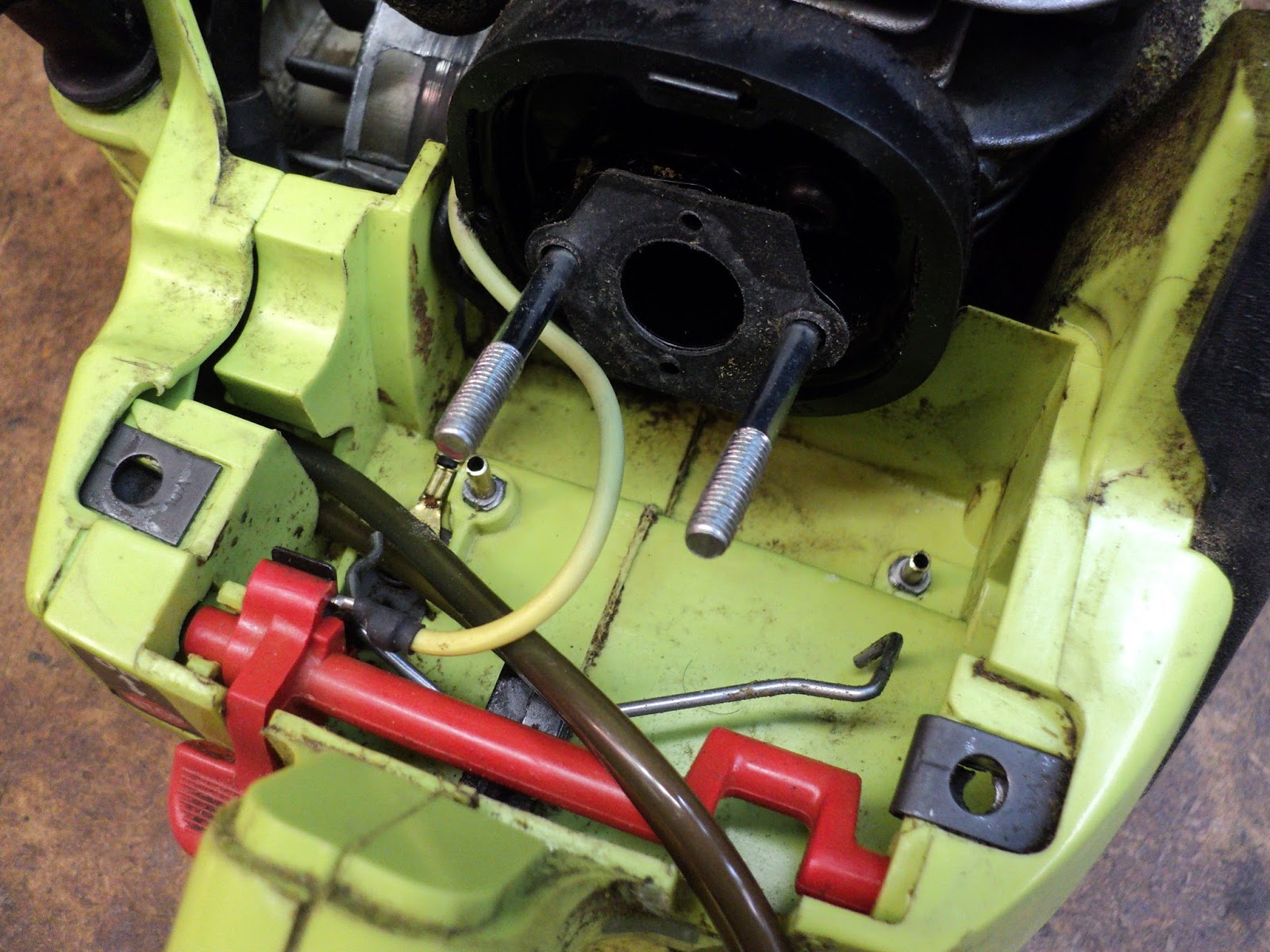
- - -

Fuel Tubing

The fuel tubing is Tygon F-4040-A, 3/16" O.D. Here's a view of the tubing arrangement at the carburetor and fuel tank. (Fortunately, the tubing on this machine is still reasonably sound. Fuel line tubing embrittlement failure is common on years-old engines.)


Note the following:

a) Bottom-most carburetor nipple to front-most fuel tank hole is the fuel supply to the carburetor.

b) Carburetor right side nipple to primer bulb left side nipple is primer suction.

c) Primer bulb right side nipple to rear-most fuel tank hole is fuel return to the tank from the primer bulb.


Carburetor Removal

1) Air Cleaner Cover off.

2) Engine Right Side Cover off.

3) Right Side of Handle off.

4) Throttle Cable Anchor removed from air cleaner body. Throttle Cable disconnected from throttle crank.

5) Crankcase Ventilation Tube disconnected from air cleaner nipple.

6) Primer Return Tube disconnected from right side primer bulb nipple.

7) Primer Suction Tube and Fuel Supply Tubes disconnected from carburetor nipples.

8) Two M5 Prevailing Torque Hex Nuts (8mm hex).

The air cleaner body and the carburetor are free to come off the engine.

Carburetor

The carburetor is made by Ruixing in China.  "129" is embossed on it, and "BFG00970" is printed on it. I can find no specific information on the unit.

I dismantled the carburetor far enough to inspect the diaphragms. The pump diaphragm appears to be quite stiff -- I wonder if that may be the cause of the hot restart trouble.

In any event, if I do go for a diaphragm kit, I'll take the complete carburetor with me. That's always a good practice whenever one is going for carburetor parts.

- - -

Carburetor Diaphragm Kit

It turns out that a Walbro item fills the bill. It's Walbro P/N D11-WYL.

- - -

Valve Clearance Adjustment

The operator's manual says to inspect "camshaft-to-rocker arm clearance" every 25 hours. (You could probably count on the fingers of one hand the number of owners who've ever actually done that.)

This machine appears to have had a great deal of use, so it might be interesting to see what the state of the valve clearances are. To access the adjustment, first remove the engine's right side cover. That reveals the valve train cover at the top of the engine, like so.


That single cap screw near the centre of the cover is the only fastener involved. Remove that screw (T20 Torx) and you can pop the cover off.

And here's what you'll see.


The gaps are measured between the cam lobes, and the rear ends of the rocker arms. The gaps fully express themselves at a point just beyond Top Dead Centre (TDC) of the compression stroke -- that's where both valves must be fully closed for the power stroke. Use the starter to hand cycle the engine to the appropriate point.

The gap specification is 0.006" to 0.008". for both valves. Use a 0.006" feeler gauge as a 'go' gauge, and an 0.008" feeler gauge as a 'no-go' gauge.

The locknuts on top are 9mm hex; the adjustment nuts' flats are 7mm across. For the adjustment nuts, you would need a thinner-than-average 7mm ignition wrench.

On this engine, the exhaust valve's gap is within spec; the intake valve just barely allows an 0.008" feeler gauge to go. The adjustment is not worth fiddling with, and that's probably the case for the vast majority of these engines over their useful life.

- - -

Final Outcome

This machine is landfill; the compression is so poor that I can't get it to run reliably.

It starts and idles, with the occasional miss. (The spark plug is clean and correctly gapped.) At wide open throttle (WOT), it will run for a little while, then it starts missing and slowing and finally stalls. It won't restart. examination of the spark plug reveals a wet plug tip.

I think what's happening is that the cylinder wall blow-by is so bad that the spark plug is oil-fouling. That's the best hypothesis I can come up with to explain what I've observed.

What I may do yet, just for the heck of it, is tear the engine down completely to get a look at its innards -- that may be an interesting exercise. We'll see.

- - -

Note:

[1] On diaphragm carburetor equipped engines, stiffened carburetor diaphragms are the cause of many starting/performance troubles. Use of ethanol-laced gasoline is guaranteed to result in stiffened diaphragms.


# # #


# # #