Wednesday, June 18, 2014

Magic Chef Gas Stove -- Stovetop Burners


This style of burner

View of burner with grate removed.


comes out with just a CCW twist, but beware -- age may have rendered the thing very tightly in place. There's a resilient ring gasket underneath the burner that may be stuck, making it difficult to twist the burner.

Grab the burner with a piece of inner tube rubber, or non-slip carpet underlay, and you'll get a good enough grip to persuade the burner to twist and come out.

The gasket under the pictured burner was brittle with age, and ended up like this when I got the burner freed.


I don't know if replacement gaskets are available separately. I put the burner back without the gasket. That works ok -- it's just that a spill can drool down under the stovetop with the gasket no longer there.

When the burner is pulled up out of place, there'll be two wires attached to it, like so.


The orange wire goes to the spark ignitor electrode; the yellow wire goes to the burner's shell (ground return). The wires are terminated with spade connectors -- just pull them free. (The connectors are different sizes -- you can't go wrong when reconnecting them.)

Two No. 6 x 5/16" pan head screws hold the ignitor in place.


With the screws removed, the ignitor can be coaxed out.


The ignitor is just a stiff, bent wire with a couple of ceramic insulators on it.


Replacement ignitors are available; ignitor repair seems to be iffy. A broken ceramic insulator can possibly be repaired with silicone sealant, sparingly applied. (I've tried using CA adhesive, but the repair didn't last.) Outright replacement of a broken ignitor is probably the best course.

And that's about all there is to a burner. The things ought to last forever.

# # #


# # #

Saturday, June 14, 2014

'Centreless' Spur Centre Installation


I needed to turn a replacement pruner handle on the wood lathe, and a complication arose with respect to mounting the blank for between-centres turning. One end of the turning blank was necessarily pre-bored to accept the tang of the pruning shears; where a spur centre's point should go, there was a void.

As it turned out, that wasn't really a problem. The four spurs of a spur centre make the spur centre self-centring, even in the absence of a centre point location. Here's a view of what I've just been on about.


Shabby though that arrangement may look, it worked fine. That 'centreless' spur centre installation got me through the entire turning job without a hitch. I sawed off that bit of waste where the spur centre had resided, and I had my completed handle.

# # #


# # #

Saturday, June 7, 2014

Roadside Find -- A Sears Craftsman 20" Lawnmower


Well, what have we here?


Something I've never seen before -- a Briggs & Stratton engine with a chrome exhaust pipe.


That appears to be a 1/2" pipe shower head stem. It's pretty sharp looking, actually.

The kill switch is a little less elegant.


At least it's unambiguous.

I don't mean to make fun here. Whoever made those repairs was working with what he had, and came up with perfectly useable functionality; there's no shame in that.

That said, there is room for improvement, and since I have little better to do, I'll go ahead and make improvements.

I'll be back when I've gotten a proper muffler for the thing.

- - -

The Muffler -- MONDAY, JUNE 9, 2014

Here's the correct muffler in place, looking as it should.


That's a Briggs & Stratton P/N 394569S muffler. It has a 1/2" NPT (National Pipe Thread) nipple that threads directly into the engine's exhaust port. That muffler can be used on any small engine with the same exhaust port thread, so long as it fits overall.

No thread sealant is needed, but it's a good idea to apply an anti-seize thread compound[1] to the nipple on installation.

With the proper muffler on it, the engine has a more civilized exhaust note.

- - -

The Kill Switch -- TUESDAY, JUNE 10, 2014

Here's what I came up with for a kill switch.


That looks better; now the mower has a 'dashboard'. Also, one doesn't have to reach right to the engine to switch it off.

- - -

The Blade

Here's a view of the blade off the mower.


Hmmm. Not only is the blade duller than a 2" x 4", it's bent. Lawnmower blades are really tough; how one can bend a blade in anything remotely resembling normal mower operation is beyond me.

Anyway, the blade is beyond redemption, and it's supposed to be a mulching blade -- I'll have to replace it.
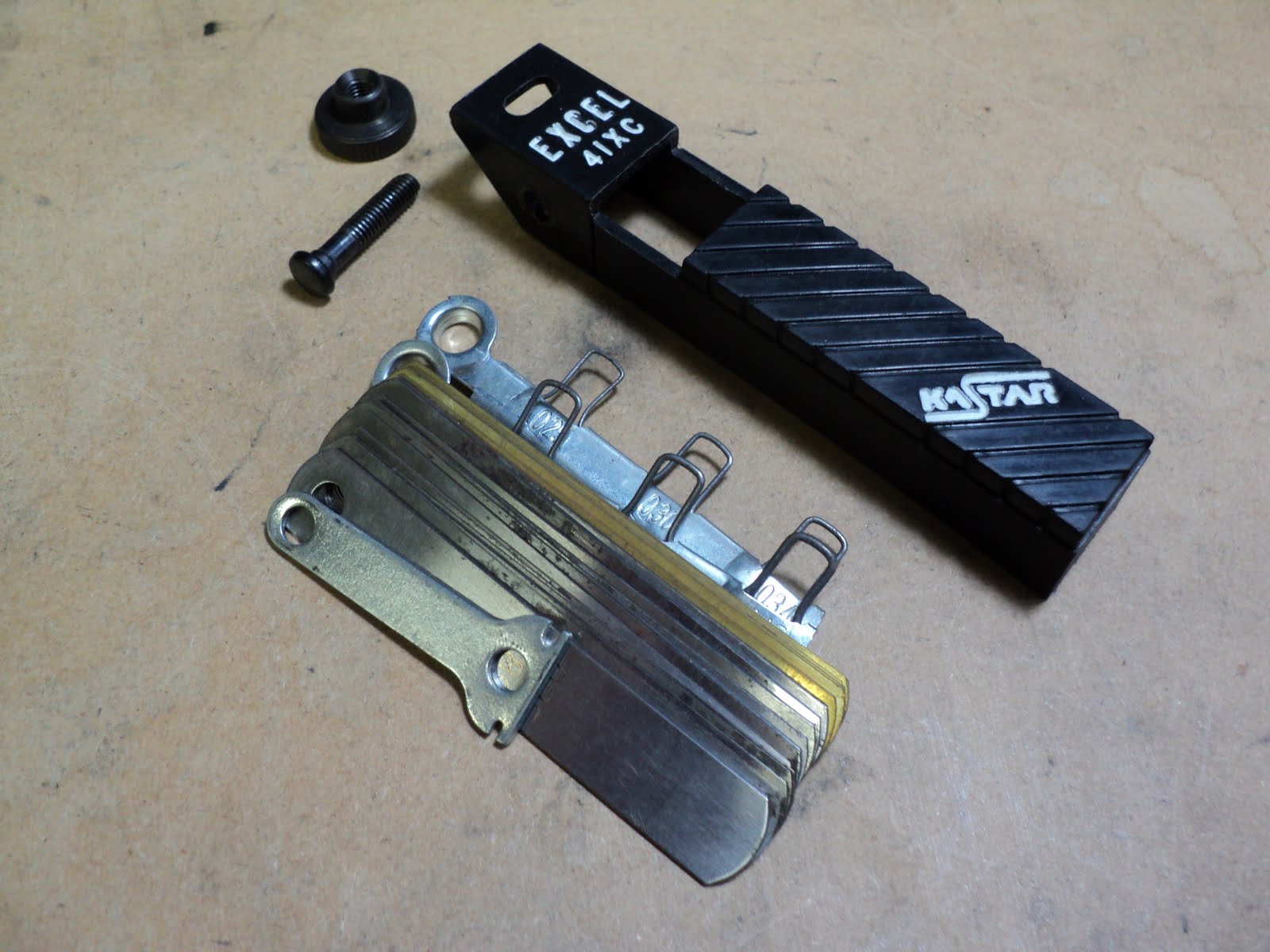
New Blade

Canadian Tire had just what I needed -- a 20" universal-replacement mulching blade, with adapters to fit many makes of mower.


The only adapter I need is that small one at the extreme left. I'll soon have this mower in fit condition to cut grass.

- - -

A Slight Problem With The Blade

In the above photo, note the slight down-sweep of the blade's ends.

When installed in the mower, the down-swept blade ends were almost peeking out from beneath the lower rim of the mower's deck -- not ideal.

The only way to elevate the blade was to elevate the entire engine, so that's what I did. I bored out three 3/8"-16 hex nuts for spacers, and came up with this arrangement at each of the engine's three mounting points.


That bought me about 1/2" of extra blade elevation, which put the blade's height within the deck more-or-less where it ought to be. The gap created between the engine and the deck proved not to be any problem at all -- there was no adverse effect on the mower's behaviour.

- - -

The Fuel Tank Cap

The fuel tank cap still screwed on, but it had a nasty dent in it. I bought a new one. (Briggs & Stratton P/N 497929.)


I suspect that dent resulted when someone left the cap off on the grass and ran over it with the mower.

- - -

Finishing Up -- SUNDAY, JUNE 15, 2014

Further routine items that needed attention:

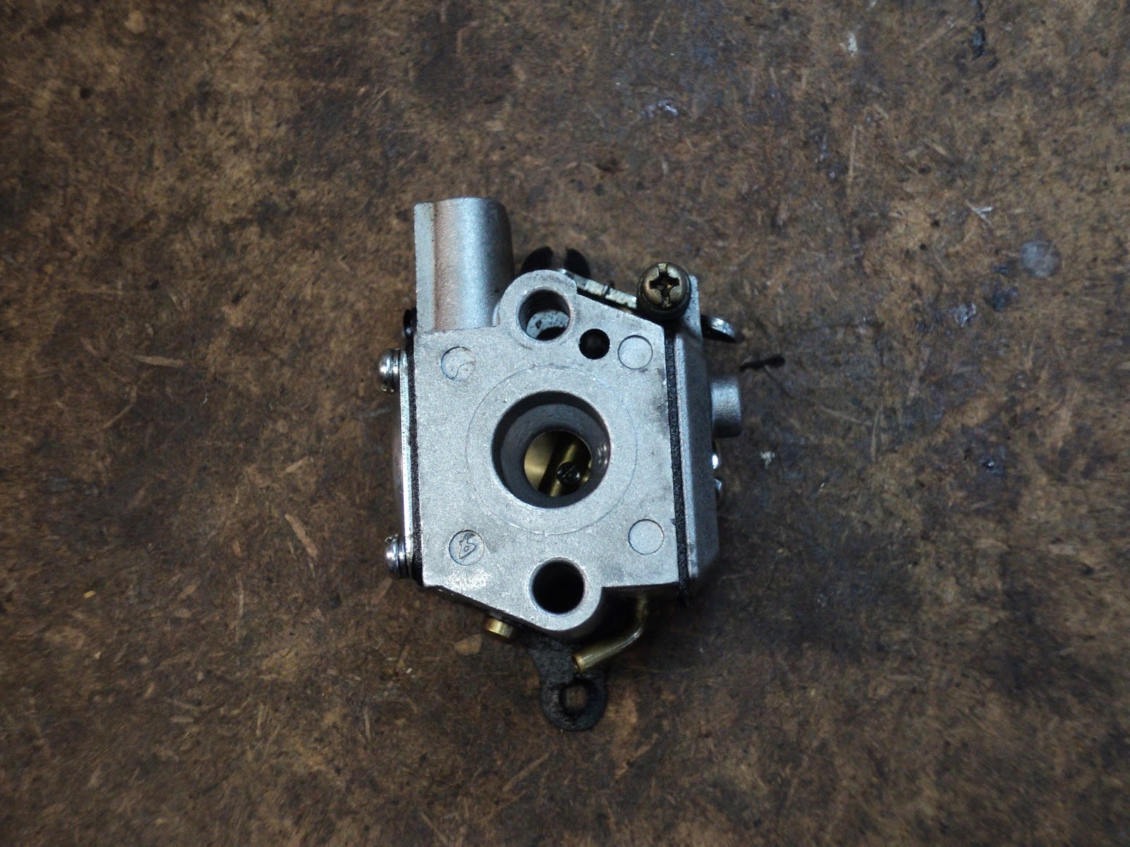
  • Air filter and carburetor/fuel-tank dismantling/cleaning. (The carb should get a new diaphragm. See this post for information on that.)
  • Spark plug cleaning and gapping.
  • Oil change.
  • Wheels oiled.
And with all that done, the mower was ready to go to work. Here it is taking a break after a job done.


The engine's compression/power isn't quite what I'd like it to be, but as a light-duty homeowner's mower, the machine is still perfectly serviceable.

Yard gear like this lawnmower can be kept going almost indefinitely with nothing more than ordinary maintenance and repairs.

- - -

Note:

[1] The stuff I use is Molykote Anti-Seize Thread Compound that I bought long ago. I don't think that product is available any longer; the compound goes a long way, and my ancient 1 lb. tin of it is not empty yet. A reader kindly informed me of Permatex No. 80078 Anti-Seize Lubricant. That product is available, and came highly recommended by the reader.

# # #


# # #

Friday, June 6, 2014

Small Engine Magneto Ignition Air Gap Adjustment


'Air gap' here refers to the space at the rim of a small engine's flywheel between the flywheel's embedded permanent magnets, and the poles of the adjacent ignition coil's laminated armature. Air gap is meant to be small -- typically a few thousandths of an inch.

Air gap is a fairly critical adjustment in small engine magneto ignition systems. The smaller the air gap, the better will be the magnetic coupling effect between the flywheel's permanent magnets, and the coil armature's poles. Reliable ignition at cranking speed demands an air gap that's well within specification. Unfortunately, meeting published air gap specifications is fraught with difficulty.

Air gap adjustment is complicated by the magnetic attraction of the flywheel's permanent magnets to the coil armature's poles. Steel feeler gauges are not useable, and non-ferrous metal feeler gauges are awkward because of their stiffness.

The best gauge I know of for the adjustment is a piece of ordinary, 20 lb. office paper. The paper is about 0.004" thick. Here's the method for using it.

1) Remove the spark plug so the engine is easy to turn by hand.

2) With the coil backed off from the flywheel, get the flywheel's magnets lined up with the coil armature's poles.

3) Insert a double thickness of paper evenly into the air gap, like so.


4) Loosen off the coil. The coil will be strongly attracted to the flywheel's magnets through the paper.

5) Tighten the coil's fasteners securely and extract the 'gauge'.

You'll end up with a tight, nominal 0.008" air gap -- about as good as it gets.

# # #


# # #

Thursday, June 5, 2014

Feeler Gauge Use


Feeler gauges are one of those seemingly simple things that no one ever says or writes a word about, but there's a bit more to their use than meets the eye.

They're called 'feeler' gauges for a reason -- you 'feel' a gap in a mechanism with them. To do that effectively, you need to be holding only the gauge leaf that's needed in your fingers, not the entire gauge set with one leaf extended.

If you're buying a feeler gauge set, look for one that comes apart easily, like the one pictured below.

Extract only the gauge leaf you need, and you'll have a gauge that will give you a much better feel for the measurement you're making.

Precise 'feel' becomes even more important on an assembly that's relatively yielding, like the printhead carriage of a small dot matrix printer. You're not dealing there with rigid machine parts, as you are when measuring valve lash in an engine with solid valve lifters. A small printer's carriage 'gives' somewhat with little force applied -- a very light touch with the feeler gauge is called for to obtain an accurate measurement when gauging printhead/platen gap. With the bulk and weight of the rest of the gauge set out of the way, it's much easier to apply that light touch and obtain a truer 'feel'.

# # #


# # #

Walbro Model WT-682 Carburetor -- Diaphragms Replacement


* * *

The need for metering diaphragm replacement is characterized by an engine that won't run with the choke fully off. Diaphragms stiffen somewhat with age, and a stiffened metering diaphragm can't deliver an adequate fuel supply to the engine. The pump diaphragm is normally replaced at the same time as the metering diaphragm.

* * *

For a typical carburetor removal procedure, see this post.

The diaphragm kit for this carburetor is Walbro P/N D20-WAT. That kit contains extra parts for other carburetor models. Select only the parts that you need for your unit.

Off the engine, the carburetor looks like this.


The metering diaphragm resides at the left side; the pump diaphragm at the right. You'll need a No. 2 Phillips screwdriver.

Metering Diaphragm And Gasket

Four 4-40 x 1/4" pan head screws w/captive lockwashers hold the metering diaphragm cover in place. Removing them will permit you to get to here.


The diaphragm and gasket will likely be stuck together, as they are in the photo.

NOTE that the gasket goes directly against the body of the carburetor.

NOTE also the small hole in the diaphragm's cover. That hole is there to admit atmospheric pressure to the outboard side of the diaphragm. The hole must be clear of debris.

The Pump Diaphragm

A single 8-32 x 3/8" pan head screw holds the cover in place. Here's view of the dismantled pump.


NOTE that the diaphragm goes directly against the body of the carburetor.

At reassembly, the throttle arm will tend to interfere a bit with getting the cover back in place. Jam the throttle butterfly part way open with the shank of a small twist drill to avoid that.

# # #


# # #

Monday, June 2, 2014

MTD Yard Machines 31cc String Trimmer -- Carburetor Removal


* * *

I would have cited the model number in the title of this post, but the subject machine is a "RECON" unit with model number "ZR766R" on it. MTD doesn't recognize that model number; I have no idea what the original, proper MTD model number is. The engine end of the machine looks like this.


* * *

You'll need a T20 Torx driver. Proceed as follows:

1) Shroud w/Air Filter Element
- Choke lever at 1/2 choke position.
- Four No. 10 x 3/4" pan head screws.
- Pull the shroud straight off over the choke lever.
- NOTE how the air filter element resides in the shroud.

The above step gets you to here.


2) Tubing
NOTE the two tubes:
- Upper tube is from the primer bulb.
- Lower tube is from the fuel tank.
- Slip the two tubes off their nipples.

3) Choke Plate
NOTE the wavy washer under the upper screw's head.
- Two No. 10 x 2" pan head screws w/captive washers.

The above step gets you to here.


4) Carburetor w/Gasket
- Disconnect the throttle cable, and the carburetor is free to come away from the engine. Its gasket will likely be stuck to it.

Here's a view of the carburetor off the engine.


This carburetor is a Walbro WT-682. If you're off to the small engine parts place for a diaphragm kit, my advice is to take the carburetor with you.

# # #


# # #

Sunday, June 1, 2014

Roadside Find -- A Napoleon Travel Q Grill


People throw out stuff that often has little wrong with it. This may be one of those items.


The gridiron inside is filthy, but I don't think the unit has been used all that much. The only thing I see that's not quite right with it is the nipple that a propane bottle attaches to.


It's showing traces of oxidation verging on corrosion. I'll unscrew it and give it a good burnishing on the lathe.

- - -

Whoops!

When I tried to unscrew the nipple, it snapped right off at its threaded shank, leaving the threaded shank inside the regulator.[1]

To make a long story short, I managed to bore out most of the shank and extract its threads without totally ruining the female thread in the regulator -- progress.

The next hurdle was to come up with a replacement nipple. I had an idle propane torch head stashed away that was of no real use to me, so I took the nipple from it and tried it. No go.

It turned out that the torch head nipple had a 1/4"-28 thread on it; the grill's regulator had an M6 thread. Hmmm.

1/4" is a little bigger than 6mm, And 28 threads per inch is not that far off from 1.0mm pitch. I rethreaded the nipple's shank with an M6 die, and there was my replacement metric part, like so.


At the left is a 1/4"-28 threaded nipple; at the right is my M6 threaded nipple made from a similar one. Problem solved.

I installed the modified nipple with blue threadlocker, to be certain of it staying put in the regulator's somewhat abused thread. Here it is in place, ready to do its job.


The grill works fine, and is in good condition overall. After cleaning up its frightful gridiron, my wife and I tried it out with a couple of frozen beef burgers -- complete success.

The only downside I see to this style of grill is fuel consumption; a grill's burner asks a lot from a little, disposable propane bottle. Grilling two burgers used up about one-quarter of a 16 oz. bottle's contents.

Aside from that quibble, the grill is a nice piece of gear, and the roadside store's prices are hard to beat.

- - -

Note:

[1] Lesson: Beware of overly-tight threaded components; they may have been installed with threadlocker.

The good news is that threadlockers are not heat-proof; sufficient heat will soften them. I should have applied a small torch flame to the nipple before cranking on it forcefully; I might have saved myself some aggravation.

# # #


# # #