I just brought this over from the garage.

It's a fine piece of gear, and the bearings appear to be ok.
Aesthetically, though, it leaves a bit to be desired. I'll tear it down and refinish it, then come up with a stand and a motor for it. If and when my son goes and does something silly like buying a house, it can be his house-warming gift from dad.
- - -
Teardown Sequence
1) Right Side Wheel
- One 15/16" A/F hex nut (5/8"-18)
- One 1 3/4" (nominal) diameter flange.
- Wheel (w/bore bushing if present).
- One 1 3/4" (nominal) diameter flange.
2) Left Side Wheel
- NOTE: You may need to restrain the spindle from turning while dealing with this item. A good way is to half-wrap the right side end of the spindle with a scrap of aluminum sheet metal, and clamp down on that with Channellocks.
- One 15/16" A/F left-hand-thread hex nut (5/8"-18)
- One 1 3/4" (nominal) diameter flange.
- Wheel (w/bore bushing if present).
- One 1 3/4" (nominal) diameter flange.
- One 9/16" long, 5/8" bore spacer. (This item is peculiar to this particular bench grinder, because of the fairly wide wire wheel that is the left side wheel. The spacer is to keep the right side perimeter of the wire wheel clear of the guard.)
3) Two Tool Rests
- Two 1/4"-20 x 1/2" square head, cup point setscrews (1/4" A/F).
- Tool rest rectangles are approximately 1" x 1 5/8".
- Shanks are 3/8" diameter x 1 1/4" long.
4) Two Tool Rest Arms
- Two 1/4"-20 x 1/2" A/F hex nuts.
- Two 1/4"-20 x 1" carriage bolts. (I may use slightly longer carriage bolts at final reassembly, so I can add flat washers and split lock washers.)
- Two tool rest arms.
- NOTE that the arms are interchangeable.
5) Two Wheel Guards
- Four 10-24 x 1/2" round head, plain slot screws.
- Two wheel guards.
6) Pulley Setscrew/Spindle w/One Bearing/Pulley/Belt
- NOTE that a press is essential for this step.
- Pulley setscrew -- remove it. It's 1/4"-20 x 1/4" cup point; 1/8" hex socket.
- Set up the machine in a suitable press, and press out the spindle w/one bearing.
- Pulley (2" diameter; 3/4" bore).
- Belt (BANROPE A-31A).
The bearings are No. 6203, sealed both sides.
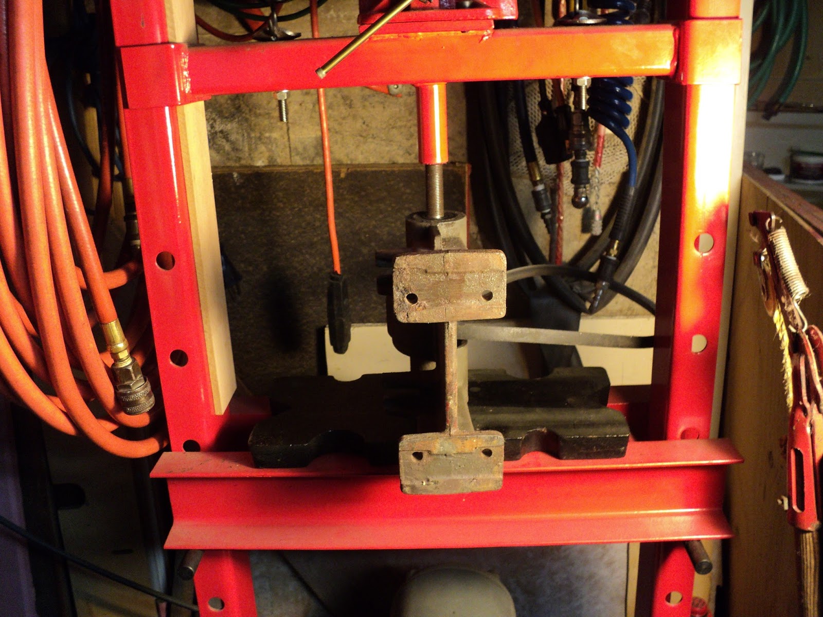
Here's a view of the chassis in my press. I've just begun, here, to press out the spindle.
7) Remaining Bearing
- One setscrew at front of casting -- 1/4"-20 x 1/4" cup point; plain slot.
- With a suitable length of suitable diameter hardwood dowel for a ram extension, press out the remaining bearing.
Here's what you end up with.

That's everything. Now I can clean up and refinish each piece prior to final reassembly.
(Note that the only way to get the R.S. bearing off the spindle is to press it off. That bearing is an interference/press fit on the spindle.)
I'll add a photograph of the finished machine here when I'm done. Also, I'll show what's involved in reinstalling the spindle and bearings -- that's a bit more intricate than taking them out.
- - -
A Bearing Installation Tool -- MONDAY, SEPTEMBER 30, 2013

Pictured is the tool I turned from hardwood for re-installing the bearings in the chassis. O.D. is 40mm, same as that of the bearings; bore is 5/8". Length is 2 3/4". Length is not critical; the adapter only has to be 'long enough'.
I've painted all the components of the grinder. When the paint has had sufficient time to fully harden, I'll get on with reassembly.
- - -
Reassembly Notes -- SATURDAY, OCTOBER 5, 2013
There's more to reassembly than meets the eye. The R.S. bearing is an interference/press fit on its spindle seat. That dictates an order of reassembly that must be adhered to. Following are some observations concerning the fits of the bearings with respect to the spindle and the casting:
a) The R.S. bearing is an interference/press fit on its spindle seat. It must be pressed onto the spindle first to begin reassembly.
b) The L.S. bearing is a free, but very close, fit on its spindle seat. When presented to its seat by the face of the tool, it can be slipped onto its seat by hand.
c) The outer races of both bearings are a 'tap-in' fit in the casting. Relatively light hammer taps will set them in place.
Note: DON'T FORGET THAT THE PULLEY AND BELT MUST GO ON THE SPINDLE AS IT'S INSERTED INTO THE CASTING.
With the spindle and R.S. bearing together, install that assembly in the casting with the aid of the tool.
Again with the aid of the tool, install the L.S. bearing. Some 'toing and froing' from side to side may be necessary. It actually would have been helpful at times to have had two of the tools, one to use as an 'anvil' under the R.S. bearing while the L.S. bearing was being installed.
Once satisfactory bearing installation has been achieved, install the setscrew at the front right side of the casting. Here's a view of what you'll have.

The remainder of the reassembly is straightforward -- it's simply the reverse of the teardown sequence.
- - -
Back In Business -- THURSDAY, APRIL 24, 2014
Here's a view of the completed restoration, powered by a salvaged 1/3 hp motor.

It's quite a nice piece of workshop gear.
This style of grinder has one slight advantage over the integral motor types -- there's no bulging motor in the middle. That can be advantageous when dealing with some clumsy pieces of work; there's a little more open space in which to manipulate work.
On the right side there's a new Norton 6" x 1/2" medium grit wheel. It's a pretty fine 'medium', so that will serve as a fine wheel.
On the left side I've temporarily installed a 5" x 3/4" wheel -- that's all I have on hand. What I'd like to get for the left side is a very coarse, very aggressive 6" diameter wheel for fast material removal. I think that combination of wheels would make for a really versatile, useful bench grinder.
Anyway, it runs nicely, and I'm pleased to see it back in service after many idle years.
# # #
# # #


