Wednesday, June 29, 2011

Gusher

Do you know what happens when you start a Tecumseh lawnmower engine with the oil fill plug not in place? You get a patio-scale version of what you see in the accompanying photograph, that's what happens.

- - -

I was giving my old mower an oil change out on the patio when some company showed up. I was pretty much done with the oil change at that point. I started the engine and let it run briefly. (It was a bit hard to start -- the engine doesn't seem to like the jerking around it gets whenever I elevate the mower to drain and change the oil.) I stopped it and unscrewed the oil fill plug to double check for correct oil level. That must have been the point at which my distractedness from company's arrival caused my brain to shut down, because I set the mower aside with the oil fill plug still off, but I didn't follow through with checking the oil level and topping it up.

It was a couple of hours later, after company had left, that I thought to get back to the mower. Having completely forgotten about the oil fill plug, but wanting to check that the engine was back to its normal, easy-starting self, I primed the carburettor and gave the cord a yank. It started right up like it ought to, accompanied by a peculiar cloud of droplets rising from it. I caught on quickly enough and stopped it, and went right to work wiping up a truly amazing amount of oil from the mower and its immediate vicinity.

I relate all that to make this observation: Individuals' ability to deal with distractions and interruptions when they're working varies widely. Mine is virtually non-existent. Distractions and interruptions cause my I.Q. to plummet to the very low double digits. Those of us who are like that need to take it into account, and at least take measures to preclude troublesome outcomes from such occurrences.

The lesson for me and for those similarly afflicted is this: When an interruption/distraction happens along, immediately take care to leave the work at hand in a 'safe' condition ( e.g. oil fill plug back in place), and simply abandon the job until the incident has passed. Then, think carefully about where it was that we left off before resuming the job. We'll save ourselves some aggravation. Granted, we may miss out on observing some interesting phenomena now and then, but I think that's a small price to pay.

# # #


# # #

Thursday, June 16, 2011

A Rotary Switch Knob Repair

Pictured below is a fairly typical tri-lite light bulb socket on a rather nice table lamp of my wife's. It has a silly little problem -- one of those things that leaves you wondering what they were thinking in the manufacturing plant.

That knob threads onto the switch's actuating spindle, which is fine, but the threaded hole in the knob is so deep that the knob threads on until it jams against the side of the socket, rendering the whole thing inoperative. Brilliant.

Happily, though, there's an easy fix for this.

The switch's spindle is threaded 4-40. That happens to be the same thread used on those little jackposts that are on older serial data port (RS-232) connectors on PCs and printers. (There's also a metric version, but the vast majority of them that I encounter are inch 4-40.) One of those jackposts will be just what I need to rectify the knob's problem. Here's a shot of the knob and a jackpost.

I'll shorten the knob by about the length of the jackposts's head, and install the jackpost in the end of the knob with CA adhesive. Then the knob will have a proper thread with limited depth.

- - -

And here's the knob made ready.

And here it is back in service.

End of problem.

# # #


# # #

Sunday, June 12, 2011

A Garden Hose Ball Valve

My wife brought me this rough looking ball valve the other day, thinking it was something I had lost. She had found it in the backyard somewhere.

I'd never seen it before. I have no idea how it could have gotten into our backyard, and I think we've been here long enough now to have found anything that the previous owner had ever lost.

I have a theory about this.

Just as small objects have a way of seeming to utterly vanish from this earth in this universe, perhaps there's a parallel earth in a parallel universe where the same thing happens. Our stuff vanishes to there, and their stuff vanishes to here.

We lost the pivot screw and nut from a pair of pruning shears awhile ago. I swear they just vapourized. Maybe some guy in some other space/time continuum is thinking the same thing about his missing garden hose ball valve, as he wonders where on 'earth' the pivot screw and nut came from.

In any event, this ball valve looks like a rugged, well made bit of gear. Underneath all that oxidation there's a thing of beauty. I'll clean it up and come up with a handle for it.

- - -

It looks like one side of the ball's seat can be unscrewed. Note the hexagonal opening in the following photo.

That's a 12mm A/F hex, but its corners are quite rounded. I happen to have an M8 bolt with an undersize (i.e. 12mm) head on it. I'll round off the bolt head's corners and try using it for a 'key'.

- - -

Here's the bolt made ready with two nuts jammed together on it for wrenching on.

And here's everything in the vise about to get wrenched.

I should mention that another possibility for a key is a 1/4"-20 coupling nut. Such a nut's hex is 7/16"(11.11mm) A/F, which is well undersize, but might work.

- - -

And here it is completely dismantled.

The ball can be slid out when it's in one of its two 'closed' positions. The stem can then be pushed inward to free it, and the remaining seat can be popped out of its recess.

Now I can carry on with getting this thing cleaned up. (And I feel much better now. I hate it when I don't know how something is constructed.)

- - -

And here it is cleaned up and back together.


Far more polishing could still be done, but I don't mean to make a career of this item; it's just a garden hose valve, after all.

It's a peculiar thing to reassemble. The ball doesn't want to seat readily on the fixed seat half. You have to screw in the removable seat half and tighten it and jerk it around and tighten it and jerk it around some more. Eventually, it all gets into place.

The screw-in seat half has to be secured with a sealant, else it can loosen. I applied Permatex Ultra Grey RTV gasket maker to the male threads only prior to its final reassembly, then left it to cure overnight.

I put a new washer in it and took it outside and tried it out. It works perfectly. So, if it's any comfort to that guy in the parallel space/time continuum who's lost his ball valve, I've done right by it.

Now, I have to come up with a handle for it.

- - -

And here it is.

That was made from a 1/4"-20 coupling nut, a 7/32" x 1 3/4" roll pin, a 2 1/2" common nail, an 8-32 set screw and some five-minute epoxy. I bored and tapped the nut to fit the valve stem's M8 thread.

I had hoped to get a perfect convex meniscus from the epoxy fill at the top end, but it's not quite flawless. It'll do, though. The nail serves to mostly fill the hollow centre of the the pin, and give a finished appearance to the end of the handle. I glued the nail in place with CA adhesive, and then back-filled the pin's slot with epoxy to complete it. Here's a view of the underside showing the epoxy-filled slot.


Now it just needs a paint job and it'll be done.

- - -

And here we are.

Not a bad outcome at all.

# # #


# # #

Saturday, June 11, 2011

Ferrule Crimping

A gun owner I know brought me this 22 calibre rifle bore brush because it had come apart on him while in use. Extracting the loose brush from the rifle's bore had been a bit trying, and he didn't want to have to do that again.

The ferrule appears to have been well crimped, but not well enough, evidently. I'll clean the pieces thoroughly with lacquer thinner, put it back together and apply CA adhesive. That's likely all that's needed for an effective repair, but I'll add another crimp just for good measure. I want to demonstrate a method for making dirt-cheap crimping dies for ferrules like this one.

- - -

I'll be crimping the top of the ferrule above the existing crimp. The ferrule's diameter there is 3/16". A 10-24 square nut should give me an effective crimping die for that diameter. (I don't have a 'formula' for this; I just go by somewhat educated guess.)

Cut an ordinary 3/8" A/F square nut in two to make a die. You want the die halves to be quite symmetrical to get a good result. Also, mark the nut so you can keep track of its halves' relationship to one another. Then, the trick is to get the ferrule along with the two die halves into the vise with everything in good alignment. That can take a bit of finessing. Here's a way to hold the work at first that's helpful.

Note the two ink dabs for keeping the die halves in correct relation. Now it's into the vise with it.

And here it is in the vise about to be crimped. Take great care with this part of the job to get the die halves aligned as perfectly as possible.

When all looks satisfactory, squeeze for all you're worth and you'll get your crimp. Here's the done deal, with the crimping die pretty much closed up.

And here's the crimped ferrule just out of the vise.

I'll trim away the squeeze-out, give it another application of CA adhesive and it'll be done.

And there it is, well and truly crimped for all eternity.

I first came up with this method when I needed to make a new handle for a flux brush. I used a length of 3/8" diameter plated copper faucet supply tubing. I did the crimps with a hex nut that I had first drilled through to all but do away with the nut's thread. Here's how the resulting crimps look.

This was crimped in two places. It got an initial full-width crimp to form a stoppage point for insertion of the bristle set, then a partial-width crimp at the very end of the tube to close up around the bristle set. I also bedded the bristle set in RTV gasket maker. As flux brush handles go, it's a cut above the usual.

So there we are; quite an effective ferrule crimping die can be had for the price of a common steel nut.

# # #


# # #

Monday, June 6, 2011

Wen Model 21 Engraver Repair

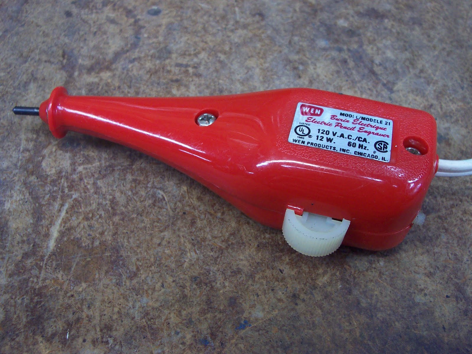
Pictured below is an old Wen Model 21 Electric Pencil Engraver that I found while rummaging around for something in a corner at my workplace.

I don't think it's ever seen much use. It's in fine condition except that its stroke adjustment screw's head is broken off. (What's left of the screw is protruding from the back end of the tool below the line cord.)

I didn't think Wen was still with us, but they're still a going concern with a website. I don't think they bother much, if at all, with the Canadian market; I never see their stuff around here.

While looking over their website, I learned that Wen Products was founded the same year as I was born -- 1951. And they still make this engraver. It's now the Model 21B. (Maybe the 'B' denotes an improved stroke adjustment screw.)[1]

In any event, this tool is well worth repairing. An engraver is good to have in the shop when you're dismantling an unfamiliar piece of machinery. You can use it to mark parts' relationships with one another to ensure that a thing goes back together exactly as it came apart. That can save a lot of aggravation at times.

Here's a view of the tool opened up. It's just two threading screws and a snap-ring to get it apart.

You can see how the stroke adjustment screw works. It's a nylon 8-32 screw with a conical end. The further in it's screwed, the more it limits the travel of that L-shaped armature, and the shorter is the engraving point's stroke.

You can't really see it in the photo, but the nylon screw has had an unsuccessful repair attempt made on it in the past. That complicates things a bit because the screw's thread has been distorted at the broken end by the repair attempt. I don't have any 8-32 nylon screws on hand, so I'd really like to find a way to salvage that existing screw. What I have in mind is to use the female portion of a binder post (aka 'Chicago screw') to recreate a handle end on the screw remnant.

- - -

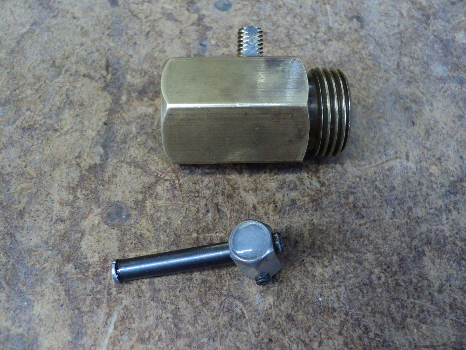
And with some difficulty, that worked. Here's a shot of the finished screw repair, along with examples of Chicago screws.

I used CA adhesive to make the screw and 'nut' assembly permanent.

The difficulty lay in cleaning up the screw's battered thread. An ordinary threading die was too thick to be workable. What I needed, in effect, was a very thin threading die that I could pass the screw remnant through to chase its thread. Since nylon is a relatively soft material, I was able to create an ersatz thread-chasing die from an ordinary 8-32 steel hex nut, like so.

I sawed through one side of a nut, and ran a tap through it to clean up the burrs left by the hacksaw. For a nylon screw, it proved to be adequate as a thread-chasing die, and got the screw cleaned up to the point that I could work with it.

Here's the engraver all back together in good working order.

I'm almost surprised that this turned out as well as it has. I was a bit concerned that the adjustment screw might tend to back out from the vibration that it's subjected to in operation, but it appears to be ok. The tool is working nicely now.

I do think, though, that the adjustment screw's design was a bit marginal. It remains to be seen whether it will need further attention, and possibly a rework of some sort to improve it. Aside from that, it's a well-thought-out, well-constructed tool.

- - -

SATURDAY, SEPTEMBER 3, 2011

Addendum

A reader in Australia informed me of something I was unaware of -- there's supposed to be a compression spring under the head of the stroke adjustment screw to keep it from wandering off its setting. The spring was long gone from the unit I had.

The Australian gentleman was of the opinion that the spring was awfully forceful for the screw. That may explain why the screw on my unit broke in the first place. As it's turned out, my adjustment screw has had so much abuse that it's now quite a snug fit in its nut, and stays put without a spring.

As I've said, the adjustment screw's design leaves a bit to be desired on what is otherwise a good tool.

- - -

SATURDAY, NOVEMBER 26, 2011

Addendum II

I noticed that someone had been googling in search of a replacement tip for this tool. I'm afraid they're out of luck on that; Wen's website offers no replacement parts for any of their portable power tools.

It would be possible to remove the stylus and chuck it in a lathe for sharpening. Provided that the chuck can be locked onto the spindle so it can be safely run in reverse, you could ever-so-carefully present a counter-rotating hand grinder wheel to it, like so.

I'll give that a whirl, and see how I do.

- - -

And here's the outcome.

Not bad, not fabulous; it'll do. I had to switch to a finer, larger diameter wheel than the one in the photo to finish it satisfactorily.

- - -

Since I had the stylus out, I cleaned the spring and stylus and the stylus' ways and applied fresh grease. There's a synthetic grease known as 'STOS' that's excellent for fine mechanisms. It's expensive; the little 2 oz. tub pictured below set me back about twelve dollars.

Gun shops carry it.

Here's a way to get the stylus' spring compressed for reinstallation of the stylus in its ways; it's very difficult to do otherwise.

The jaws gripping the stylus are those of a small set of long-nose Vise-Grips (Vise-Grip model 4LN). Be careful with letting go the Vise-Grips once the stylus is in position -- that spring wants to extend quite energetically.

- - -


SATURDAY, DECEMBER 10, 2011

Addendum III

I noticed something about the tool's operation that I don't much care for -- quite a lot of vibration is expressed at the head of the stroke adjustment screw when the tool is running. That's a source of needless noise, and it can't be good for the screw.

I suspect the reason for it is the way the stroke adjustment screw's nut is housed -- it's just a loose slip fit in its recesses. Epoxy can be put to use as a filler, even in places that need to be taken apart. I'm going to see if I can create a 'zero-lash' fit for the nut with epoxy, and see if that has any good effect on the tool.

Here's a close-up view of the nut in its right side recess. You can see that it has a fair bit of clearance in back of it.

That clearance makes for a fairly mobile nut, even when the tool's casing is all closed up. I'll 'bed' the nut in epoxy on that side.

- - -

Here's the nut's recess sufficiently filled with slow-setting epoxy.

And here's the nut in place.

Needless to say, there was some squeeze-out that I had to clean up. I'll leave that to harden overnight.

- - -

There was a little bit of epoxy-fouling of the nut's thread; a chase with an 8-32 tap took care of that.

Now that I have the nut immobilized on one side, I have to do the same for the other side, while at the same time ending up with a casing that can still be taken apart. That's a little tricky.

- - -

Here's a view of both casing halves just prior to assembly for fully bedding the nut.

I've inserted a screw at either side of the nut, so the nut can't fill with epoxy, and each screw will be readily removable. I've lightly smeared the exposed surfaces of the nut, the screws and the surrounding lands with WD-40. I've filled the left side nut recess with epoxy. It's time to put it together, clamp it and leave it for the epoxy to cure, like so.

- - -

It did work out, but not quite as I expected. Here it is opened back up after the epoxy had fully hardened.

The nut adhered where I thought I'd prevented it from adhering, and came free from where I thought I'd adhered it. Beats the bleep outta me.

Anyway, I appear to have what I was after -- a zero-lash fit for the nut that can still be taken apart. I'll take the two barrier screws out and clean up what squeeze-out there is under them.

- - -

The nut's thread wanted chasing again -- there was a tiny bit of epoxy incursion. Here it is with the stroke adjustment screw back in place.

'Looks like it'll work. I'll reassemble the tool and see if all this has had any good effect.

- - -

Splendid! (There's a word you seldom see or hear anymore.) A splendid outcome.

The vibration at the head of the adjustment screw is now all but entirely suppressed. It's easier to adjust. I can't say that the tool is quieter, but it's smoother -- it no longer sounds like it's thrashing about inside.

So there we are. Epoxy is versatile stuff, and can be put to use in unorthodox ways to very good effect.

- - -

Note -- SUNDAY, NOVEMBER 27, 2011

[1] I see that Wen has done a redesign. Their new engraver is the '21C', with a revised stroke adjustment. 'Took them long enough to get around to that.

# # #


# # #

Sunday, June 5, 2011

Weed Eater FeatherLite SST Fuel Tank Repair/Replacement


A Note re Tubing and an Update -- TUESDAY, APRIL 29, 2014

I didn't try to obtain proper fuel line tubing for this; I just used stuff that I had on hand. The black tubing pictured further down didn't work out -- it wouldn't take immersion in fuel. It swelled up and came off its nipples.

I replaced the black tubing with intravenous (IV) supply tubing, and that has worked remarkably well. It still stiffens and needs to be replaced periodically, but it holds up better than the original stuff did. I imagine that any small engines repair outfit could supply the 'correct' tubing, if you have nothing suitable on hand.

All in all, my repair method shown here has proven to be sound, and I've applied the same method to the short 'primer overflow' tube as well. The trimmer is still operational after nearly three years.

- - -

I've also had occasion just recently to do some repair work on the Zama carburetor -- it needed new diaphragms.

A carburetor removal procedure is here.

Diaphragm replacement is shown here.

* * *

When I went to start up the trimmer for the first time this season, it was no go, no way. A little investigation revealed that the fuel supply tube in the fuel tank had turned into something with the flexibility of uncooked pasta. The fuel pickup/filter had broken off entirely. I fished it out of the tank and here's what I had.

Before I go to a parts dealer and hand over a wad of after-tax dollars for a new fuel tank, I'll look into repairing this.

- - -

First thing is to disconnect the two tubes at the carburetor -- they just slip off their nipples.

The tank is attached to the engine's outermost cowl piece. That cowl/tank assembly is fastened in place by five screws. (That cowl piece is also the end-cap for the engine's crankcase. Once that's off the crankcase is wide open, so you want to take care about cleanliness.)

The screws involved are all washerhead types with T25 Torx recesses. The four that go into the crankcase are 10-24 x 3/4" thread-rolling screws. The one screw at the top of the cowl is a No. 10 x 5/8" thread-forming screw.

The fuel tank is fastened to the cowl piece with two No.10 x 7/8" thread-forming screws w/flange washers.

And that's all it takes to get to where you could replace the fuel tank if you needed to. The only 'complication' is that, as I mentioned earlier, you've unavoidably opened up the engine's crankcase. With the cowl piece removed, here's how the engine looks.

Needless to say, you don't want any grit to get in there. At reassembly, I'll apply some RTV gasket maker to the face of that gasket. A crankcase leak in a two-stroke engine is fatal to engine operation.

- - -

The cowl piece and fuel tank were just filthy with sticky, tenacious two-stroke muck, so I gave them a good scrubbing in the parts washer.

Here's a shot of the business end of the cleaned up fuel tank. (It's not a very good photograph. Digital cameras seem to have trouble with certain types of rounded surfaces up close. I've noticed the effect before.)

That tube that's still left on the tank is the primer's 'overflow' tube. It's condition is marginal, but it's still serviceable.

I tore away the old supply tube remnant entirely. It appears that what the factory does is they simply pull the new tube through a tight-fitting hole. The tube's resilience seals it in the hole.

I don't have identical tubing to use for a replacement, but I do have some tubing on hand that fits the carburettor's input nipple and looks more-or-less suitable. Its outside diameter is just shy of 1/4" -- considerably larger than the original tubing. If I can come up with a double-ended nipple that I can install in the wall of the tank, I can make it work. This should be interesting.

- - -

And here's my double-ended nipple.

It's a piece of 5/16"-18 threaded rod bored through to accept a length of 1/8" diameter brass tubing. I soldered it together. Note the wrenching flats. They'll take a 7/32" wrench come installation time. Here's how I secured the threaded rod in the vise while I filed the wrenching flats. It's a good way to clamp any threaded piece of work with no jaw mark damage to the threads.

Saw through a hex nut and you get a rudimentary 'collet' in which to hold the threaded rod without marring it.

- - -

Next up is to drill and thread the fuel tank to accept the new nipple, then install the nipple and replacement fuel supply tube.

- - -

Here are the nipple and supply tube in place. I just have to attach the filter and tuck the tube/filter inside.

I used a 1/4" drill for a tap drill. 1/4" is 0.007" smaller in diameter than the letter size 'F' drill you're supposed to use for a 5/16"-18 tap. My thinking there was to try to get a better than 75 percent thread cut in the relatively soft tank wall.

I've used CA adhesive on the nipple's threads. I'll reassemble everything, give the crankcase gasket's sealant some time to cure and try it out with freshly mixed fuel.

- - -

Here it is all back together.

And I got it running after a bit of an ordeal with the carburettor. At first it simply would not start. I took the carburettor off, dismantled it somewhat and flushed and blew out its passages. 'Put it back together and it still wouldn't start. 'Took the primer bulb and body completely apart, blew out its passages, put it back together and it started and ran fine. Something in that mystifying little device must have been plugged. I suspect that the embrittled, broken tubing must have shed some particles that got drawn in while trying to start the engine.

Anyway, my fuel supply tube repair looks good so far. I don't know for certain whether the tubing I had on hand to use is fit for continual immersion in gasoline. I imagine I'll find that out soon enough. As far as I know, CA adhesive has very good solvent resistance, so the nipple's installation should be sound. I think I can safely say here that making and installing a double-ended nipple is a good way to repair one of these fuel tanks.

# # #


# # #

Wednesday, June 1, 2011

A Bubble Level

I've had this little bubble level sitting in a drawer for years. I must have gotten it from an old colour laser printer that was being scrapped. I've finally thought of a use for it, but I'll want it to have a round base. 'Time to remove it from that steel rectangle and make it a proper base.

A 7/16" plate washer will serve for a base.

The screws are M2x6mm, and I don't have an M2 threading tap. I'll see if I can fake it with a bit of interference fit trickery and CA adhesive.

A proper machinist might sneer at some of my methods, but I find masking tape to be invaluable as a layout aid. Here's the washer covered in masking tape with the three hole locations transferred to it with a sharp pencil.

My close-up vision is not what it used to be, and a layout done on masking tape is helpful to me because of the tape's 'impressibility'. With points spotted on masking tape, I can make small impressions in the tape at those points with an awl point while viewing the work under an illuminated magnifier. Those impressions in the tape then give me a tactile way to confirm that I'm locating the point of a centre punch correctly.

Here's the washer having just been drilled with quite remarkable accuracy.

Those holes were drilled with a No. 49 drill. I'll explain how I arrived at that size of drill.

Miking the screws gave me their diameter as 0.075". A No. 49 drill is 0.073" diameter. There's my interference fit. I'll be forcefully installing the screws in holes that are 0.002" undersize.

- - -

And here's the completed level.

That more-or-less worked. I would like to have had slightly longer screws -- one of the three screws stripped instead of gripping; the screws only had a couple of threads worth of engagement. The other two went in ok. I applied CA adhesive to the ends of the screws from the underside of the washer so it could wick in around the screws.

I think I can call that a success. For what little is being asked of those screws, my interference fit w/CA adhesive added is quite adequate. Now I can get my wife's miniature birdbath installed with its bowl level. (I did mention early on that I had thought of a use for this thing. Here it is. Scroll way down.)

# # #


# # #