Monday, May 26, 2014

Tecumseh Primer Bulb Crud


Here's why you never neglect to remove the primer bulb when cleaning a Tecumseh carburetor.


That's from an engine that was left outside idle for a long time. I had cleaned the carburetor, but I hadn't removed the primer bulb. I imagine the crud may be condensation leavings of some sort.

Anyway, the engine was hard-starting, and the primer bulb felt mushy. I cleaned away the crud, replaced the primer bulb and the hard-starting was gone.

# # #


# # #

Saturday, May 24, 2014

A Bicycle Fender Stay Retaining Post Repair


The M5 stud on this retaining post from my wife's bike stripped on me this afternoon.


I'll have to replace that threaded stud portion of the post. I don't have the full set of M5 taps -- taper, plug and bottoming -- that I'd like to have for this, but I do have a full set of 10-32 taps. 10-32 is as close to M5 as 'damn' is to swearing, so I'll go that route.

First off, I'll cut away the M5 stud, and drill the post for 10-32 tapping. (No. 21.) Then I'll tap it 10-32.

- - -

Here's a view of that done.


I'll cut that stud next to the post down to the correct length, and install it with CA adhesive.

- - -

And here's the finished post all wire-brushed and fit for installation.


- - -

Addendum -- SUNDAY, MAY 25, 2014

It was brought to my attention that I've neglected to show where this part goes. Here's a contextual view of the part doing its job.


# # #


# # #

Wood Lathe Mandrel Turning


I have an old fireplace tool that's missing its wooden handle, like so.


The solution is obvious -- turn a new handle on the lathe. How to do that is not so obvious.

The handle must be bored through for its retaining rod. Boring it after it's been turned is a pretty iffy proposition. Boring the blank before it's been turned is more like it, and that leads to turning it on a mandrel, like so.


That mandrel is a length of 1/4" threaded rod, centre-drilled at one end to accept the nose of the tailstock's live centre. Let's see how this goes.

- - -

And here's the handle, as good as it's going to get.


I don't claim to be a masterful wood turner, and that's not the most graceful handle imaginable, but it will do.

Let's see how it looks attached to the fireplace tool's shank.


All in all, that's not a bad outcome.

I'll give the handle a tung oil finish, and I'll have the use of the tool back.

# # #


# # #

Wednesday, May 21, 2014

Bicycle Pedal Overhaul


Bicycle pedals should rotate smoothly, with just a hint of bearing preload. Grittiness or 'lumpy' rotation should be attended to. A pedal that rotates very freely is grease-starved.

This post deals with what I believe is the commonest style of bicycle pedals; i.e. those with a 9/16"-20 threaded stud for attachment to the crank arm, and a ball bearing at either end.

- - -

Removal

Pictured below is a fairly typical right side pedal.


It has 15mm A/F wrench flats on its spindle, and a right hand (conventional) threaded stud. Its left side mate will have a left hand threaded stud. The spindles are usually marked 'L' and 'R', but it's not difficult to tell the difference by eye.

When loosening a pedal to fully unscrew it, you may need to get some leverage on the crank arm. Here's a quick-and-dirty way to do that.


Take care to get the big adjustable wrench centred and snug, so it doesn't slip on you. I've yet to have a pedal defy that arrangement. Pedals aren't usually all that tight, and I haven't encountered a seized one so far.

Disassembly

The outboard end will have a cap that can be pried off, like so.


Revealed are a locknut, a keyed washer and the outboard bearing cone.

The locknut pictured here is 12mm A/F. (I've encountered some oddly dimensioned locknuts that needed an adjustable wrench.) Mount the pedal in a mechanic's vise by its wrench flats to loosen the locknut.


You'll use the same vise setup later to adjust and lock the outboard cone.

With the locknut removed, dismantle the pedal over a bin so that you can't lose anything. You'll end up with this.


This pedal employs eleven 5/32" diameter balls at each end, although its inboard balls seem to be a bit undersize -- I'll have to keep them segregated. You may encounter other ball sizes and counts.

A tea caddy is good for handling tiny parts in the parts washer.


Get everything immaculately clean, and you'll be ready to reassemble the pedal.

I use white lithium grease for the bearings, and I'm inclined to be fairly generous with it.

Lay grease in the cups then, with tweezers, lay the balls in the grease. The grease will retain the balls. Here's a view of the outboard bearing ready for the spindle and cone.


Excess grease can escape as it pleases. With plenty of grease in the bearing, the bearing will be reasonably well protected against water incursion.

With both bearing cups greased and loaded with balls, reassemble the pedal and get it back in the vise for adjustment.

As I said earlier, a pedal should rotate smoothly, with just a hint of bearing preload. In theory, the keyed washer is supposed to prevent the locknut from altering your cone adjustment as you tighten the locknut. In practice, that doesn't work out so much. Bearing adjustment is a trial-and-error process. You just have to keep at it until you get it right. This pedal didn't give me a hard time -- it settled into proper adjustment without much retrying. Here's a view of the pedal's outboard end all greased and adjusted and locked up.


Replace the cap and you're done.

- - -

Notes:

Following are some notes on pedal maintenance.

  • Ideally, bearing cups, balls and cones should show no trace of corrosion. In the real world, those items may be less than perfect. Unless the bike is meant for hard, frequent riding, you can probably get away with just cleaning and regreasing.
  • Pitted balls should be replaced. Any bike shop worthy of the name ought to carry bearing balls. Alternatively, you can find them on-line. In my experience, ball sizes are fractional inch measure. A fractional-inch/metric vernier caliper is a handy thing to have for bicycle work. Bicycles tend to have quite a mix of inch and metric components in them.
# # #


# # #

Monday, May 19, 2014

A Method For Cutting Steel Bicycle Cable Jacket


Steel bicycle cable jacket is tough, saw-defying stuff. The best way I know of to cut it is with one of Dremel's large-diameter (1 1/4"), reinforced cut-off wheels. Here's how to go about it.

1) Wrap a bit of masking tape around the jacket where you mean to cut it, and mark your cut-off point clearly.


2) Clamp the jacket end gently in a vise, and cut through the jacket with the cut-off wheel. Cut the jacket a little bit long.


3) With a belt sander/grinder, grind the jacket end squarely to finished length. Go easy so you don't heat up the jacket and melt its plastic sheath.

4) De-burr the end A/R and blow the jacket through with compressed air to clear out any grit. You'll end up with a nicely squared-off jacket end at an exact length.


# # #


# # #

Thursday, May 15, 2014

An Oil Removal Apparatus For Lawnmower Engines Without Drain Plugs


Our newish lawnmower has no oil drain plug in its engine. That appears to be becoming standard practice on rotary mower engines -- you drain the oil through the filler tube by tipping the entire machine over.

That's not exactly my notion of progress. One hopes that the automakers don't take up the idea -- then we'd see the price of oil changes go up more than a bit.

Anyway, the practice of draining oil through the filler tube struck me as needlessly inviting a huge mess, especially with my Briggs & Stratton engine. The configuration of mower-handle/engine/filler-tube just doesn't lend itself to a graceful procedure.

It dawned on me that I have a vacuum pump and a brake bleeding vessel, so I thought, "Why not apply them to oil removal?" I rigged up this.


And that worked fine. The only shortcoming was the small size of the vessel -- I had to stop and empty it a few times to get all the oil out.

The solution, obviously, was to adapt a bigger vessel, like a sauerkraut jar. A couple of 1/8" pipe fittings, some 7/32" diameter brass tubing and a few minutes at the lathe got me this.


Functionally, it's the same as before, but with a big enough jar to empty a crankcase at one go. Here's a view of the apparatus on the job on a Tecumseh engine.


It works. That beats wrestling with the entire mower to pour out its oil.

- - -

Notes:

Following are some notes, in no particular order, on construction and use of the apparatus:

  • The jar lid's gasket must be in good condition. A jar lid that leaks vacuum won't work.
  • Brass tubing is available at hobby shops.
  • Use the apparatus on a warm engine, so the oil will be free flowing.
  • Oil capacity in rotary lawnmower engines is typically about one pint -- roughly 500ml. A 750ml jar serves with plenty of margin.
  • Just about any source of suction will work. If it has a check valve, it should also have a purge valve, so that suction can be easily terminated when desired.
  • One could use one's mouth as a suction source, but that would probably be ill-advised.
  • The only downside to the large jar is that it takes a fair bit of pumping at first to establish a vacuum. Other than that, the apparatus works nicely.

# # #


# # #

Saturday, May 10, 2014

Sturmey-Archer 3-Speed Hub Teardown


I have an ancient 3-speed bike that's been languishing under a tree for a long time. The rear hub feels a bit gritty when I turn it. I'd like to have the bike roadworthy again, so best I attend to the hub and get it clean and re-lubricated before I put the bike on the road.

The rear hub is a Sturmey-Archer 'AW' series hub -- the 'classic' hub of which zillions were made. It's not a difficult device to deal with. For all its apparent complexity, it's a pretty straightforward thing to dismantle, clean and reassemble. Just keep things in order as you go.

- - -

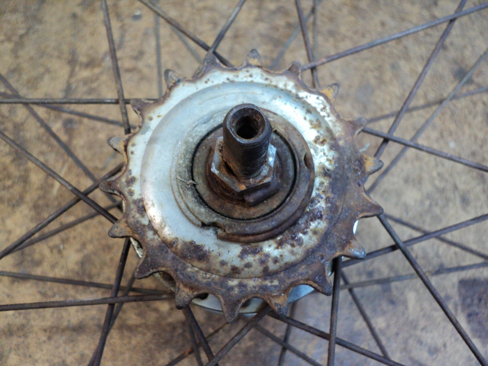
Here's a view of the sprocket side of the hub with the indicator chain, and the fastening nuts and washers removed.


Disassembly

Note the snap-ring. That has to come off to remove the sprocket, and two spacer washers and a dust cap that are underneath it.

Next is the spindle bearing cone. You'll need 15mm and 16mm spanners. Note the special keyed washer that fits over the end of the cone. You may need to hold the spindle from turning as you completely unscrew the jam nut and cone. The spindle is 8mm A/F.


And here we are with the cone removed.


Exposed for removal are the clutch spring and its cap, and the four-pronged driver. Remove those three items. Here's a view of them off the hub.


In the second-last photograph, note the large ring showing one of its two notches. That's called the 'ball ring', and it has to be unscrewed[1] in order to get at the remaining components of the hub. The factory no doubt has a spanner for that, but I can't see that such a spanner is available anywhere. You're left with hammering at a notch in the CCW direction with a suitable punch. The method does work if you keep at it. The ring on my hub was very obstinate, probably from having been undisturbed for so long, but I did finally get it to unscrew.

Here's a view of the removed ring and its underlying components.


All that remains in the hub are the left side cone and its bearing, and the spindle. Before removing the cone, note and record the length of the spindle that protrudes beyond the cone's jam nut; you'll want to get that affair back together exactly as it was with respect to axial dimension. Here's a view of the removed spindle.


And that's it. All that's left in the hub is the left side spindle bearing. I'll leave that alone and just clean it in place. Everything can get a session at the parts washer, and it'll all be ready for reassembly. I found one broken pawl spring that I'll have to get a replacement for. Also, the plastic oil port/cap is a ruin, and should be replaced. Aside from that, the hub appears to be in fine condition, and should have many trouble-free miles still in it.

Pawl Spring

Parts are not readily available for these things, it turns out. I had to fabricate a pawl spring from some straightened out spring wire. Here's what I came up with.


My spring is on the right. It's slightly heavier gauge wire than the original, but it still fits. (The original spring on the left is made of 0.012" diameter wire.) My spring leaves a bit to be desired, but it'll work.

Oil Port/Cap

It turns out that the hole for the part is threaded M6. I cut and ground down a screw to a very short length, and that can serve as my new oil port cap. Here's the short screw.


I'll have some reassembly notes to follow.

- - -

Reassembly -- SUNDAY, MAY 11, 2014

Lubrication

I packed the bearings' ball cages with white lithium grease, and oiled everything else liberally with light mineral oil. I'll give the hub a final squirt of mineral oil through the oil port before I put it on the road.

Bearing Adjustment

Ideally, you want to end up with very light bearing pre-load, with no perceptible play at the wheel rim.

The keyed washer at the right side cone makes it difficult to make fine, incremental adjustments -- the washer forces quarter-turn increments of adjustment onto the right side cone. I made my final pre-load adjustment at the left side cone, where there's no keyed washer. It's a trial-and-error process; just keep at it until it's satisfactory.

- - -

Note:

[1] The ball ring has a two-start thread. I've read warnings that it's important to mark the thing before removing it, so that you can get it back together with the hub's shell the same way. While I'm inclined to agree that machine parts should always go together as they were, I think the warnings in this case are pure superstition. I can see no good reason for them whatsoever.

# # #


# # #

Saturday, May 3, 2014

Bicycle Crank Cotter Pin Removal


Bicycle crank cotter pins are stubborn things. There's a sure-fire way to remove them that does not involve a hammer,[1] but it does require a small mechanic's vise like this one.


That's a 3" vise. That size is big enough to do the job, but small enough that it can be manipulated as a 'hand tool'. I can't recall what I paid for it, but it was on special at Canadian Tire and wasn't expensive. (I've removed the vise's swivel base to lighten it a bit.) Make certain that the vise's screw and screw-head thrust-face are well lubricated.

Cotter Pin Preparation

Loosen the cotter pin's nut, and back it off to where its outer face is just past the end of the threaded stud, like so.


At the head end of the cotter pin, place a 3/8" (9/16" A/F) hex nut that's been bored out to fit over the cotter pin's end (3/8" diameter typically). The nut must be taller than the height of the cotter pin's protruding end.


Now, take the vise and clamp its jaws squarely onto the prepared cotter pin.


You'll need a big adjustable wrench for leverage on the vise.


Now crank on the vise's screw for all you're worth. (You may need to add a suitable length of pipe to the vise's handle for increased leverage.)

Eventually, there'll be a big "POP", and the cotter pin will be free.

* * *

CAUTION

When the pin 'pops', the vise may suddenly fall away. Be clear of its path. Wear eye protection. The force involved in this procedure is huge. Unforeseen stuff can happen.

* * *


And there we are -- the cotter pin is out, and not a single hammer blow was struck.

I can't say that I've done this procedure often, but it has yet to fail me.

- - -

Note:

[1] Hammering setups like the one pictured below are hogwash.


The wooden 'anvil' will absorb much of a hammer blow's force. What's pictured is a recipe for damage and frustration -- it's not a reliable method for removing cotter pins.

# # #


# # #

Friday, May 2, 2014

A Stand For Bicycle Maintenance Work


A bicycle is a graceful machine when it's up on its wheels out on the road. When it's at a standstill for work to be done on it, a bicycle is an awkward, unwieldy piece of hardware.

I have an ancient J.C. Higgins bike that's in need of some serious repairs, and I've long had in mind a way to construct a solid stand for bicycle work. I cobbled together a crude prototype of the stand, and it looks to me like I'm onto a good thing here. Here's a view of the stand doing its job.


The bike's wheels are well up off the ground and fully operable. I can work on any part of the bike without it wanting to flop around on me.

I'll update this post with details of the stand's construction once I've made some refinements.

- - -

The Base -- FRIDAY, MAY 16, 2014

Here's a better view of the base.


It's two discarded disc brake rotors joined by a length of 2" x 4". The flange at the centre is 1" pipe. The carriage bolts are 1/2" x 2 1/2". (The stud holes in the rotors were slightly undersize for 1/2" carriage bolts. I had to grind them out a little with a hand grinder to fit.)

I'll be back when I've refined the mounting post, and it's no longer held together with a c-clamp.

- - -

The Post And Mount -- SUNDAY, MAY 18, 2014

Here's a view of the post and mount components almost ready for final assembly.


From left-to-right we have --

a) The mount: That's a cut-off upper part of an old two-legged kickstand.

b) The mount/post interface: That's a seven inch length of hardwood that I turned on the wood lathe to a suitable diameter. It's a snug, but 'twistable', fit inside the 1" pipe post, so it can be turned as needed to align the mount with the base of the stand. I flattened two opposite sides of its upper portion with a spokeshave, so it would fit the mount.

c) Some 10-24 fasteners for securing the mount to the interface. I've still to drill the holes for those.

d) The post: A 12" length of 1" iron pipe, threaded at both ends. I've cut two opposed slots in the upper end, so it can be clamped 'collet-style' onto the hardwood interface.

e) A 1 1/8" (nominal) muffler clamp (saddle clamp) from an auto supply. The one pictured is an ROL Exhaust P/N 510118. I'm sure there are other makes of much the same thing. I had to file out the saddle's opening a bit to improve the clamp's fit on the post.

The Post/Mount Assembled And Installed

Here's the completed upper part of the post/mount.


And here's the whole affair outside holding up an old Raleigh.


The mount is a marginal fit for the Raleigh; the Raleigh's rear fork tubes are farther apart than the J.C. Higgins', but nonetheless the mount does hold fast. I'll give some thought to how I can improve the mount's 'universality'; possibly with hardwood clamp pads and a longer bolt.

I got that bike in place and secured without help, but it would be nice to have an assistant when you're mounting a bike on a the stand.

The stand really shines on transmission work -- it gives you full, unhindered operability of the crank and rear wheel, so you can easily make adjustments and tell what's going on.

# # #


# # #