My son has been clearing out my deceased father's garage, so he'll have a place to restore an old car, and he's been finding the odd interesting bit of gear, like this woodworking vise.

On the front it says, "THE N. SLATER CO. LTD. HAMILTON CAN".
N. Slater currently exists as
Slacan Industries Inc. I don't think they make woodworking vises any more, though. I emailed them to inquire about the vise's likely age, and they never replied. I should thank them for reinforcing my opinion of the corporate world.
This thing is just begging me to restore it to pristine condition; I guess I'll have to comply. Consider it a work in progress. I'll update this post as I go along with it.
- - -
MONDAY, DECEMBER 26, 2011
The Dog
This leaves a bit to be desired.

A vise dog is something I never have use for, but this is a restoration so I have to come up with a sound facsimile of the original part.
I'll have to find some steel bar stock, 1/2" x 3/4" in cross-section, and 2 5/8" long. That's going to be a challenge; I have nothing like that on hand.
- - -
The Jaw Facings
What's currently on it for facings is two wretched, undersize pieces of 10mm plywood. That has to go and be replaced with proper hardwood facings, 3 1/2" x 7 1/4". I have two excellent pieces of oak on hand for that.
- - -
The Rail-Rod End Terminations
Yuck. A couple of folded over nails.

I'll replace those with the correct size of cotter pins, and add two close-fitting flat washers or something for a more elegant rod end termination.
- - -
The Handle
See the first photo above. It's currently a 12 1/2" length of 15/16" diameter hardwood dowel, with a screw in each end for retention. It's actually not bad; the length is good and the diameter is about right. I might keep that, but I'll have to come up with a better-looking treatment for handle retention.
- - -
WEDNESDAY, DECEMBER 28, 2011
The Rear Jaw/Foundation and the Nut

The nut is interesting; I've never seen this done before.
The nut is self-retaining. Its length is it's axial retention, and the 'wings' are its angular retention.
The nut's overall length is 4 1/2". The thread in it is only at the front (under the wings); the thread extends back 1 3/8", then the rest of the nut's length is just hollow.
That metallic paint looks pretty chintzy -- I'll paint it the same colour as I paint the jaws. (I haven't decided on a colour yet. For a restoration, I should stay true to the original, but that grey looks dismal to me. A dark blue similar to Record blue would look good.) Anyway, the next stop for the nut is the parts washer tank for a thorough degreasing.
- - -
The Screw and the Crank-Tee
The only way to get the screw out is to grind the peening off the end of a big rivet.

Here goes.
- - -
THURSDAY, DECEMBER 29, 2011
Stymied
That didn't work out worth a bleep.
It's not often that I have to say I'm stymied, but I'm stymied. It looks to me like that rivet was installed with an
extremely tight interference fit, then peened only to look right. They could have forgone peening it; nothing would budge that rivet. I'll have to clean the screw and paint the front jaw and the crank-tee with the screw still in place -- clumsy but doable.
- - -
TUESDAY, JANUARY 3, 2012
The Screw
That bit of failure behind me, I must point out an interesting feature of the screw. It's an Acme, two-start thread. Here's a view of the end of it.

The photograph reveals it poorly, but what's pictured is two interleaved threads -- hence, 'two-start'. (I've daubed the starting points with correction fluid to make it clearer what I'm on about here.)
Linearly, the thread
appears to have a pitch of 4 tpi (four threads per inch). A 4 tpi thread would have a lead (linear advancement per revolution) of 1/4". But this thread has a lead of 1/2" -- one revolution of the screw moves the front vise jaw 1/2". That's because it's actually two interleaved 2 tpi threads (two threads per inch gives a lead of 1/2"). The apparent 4 tpi thread is really two 2 tpi threads -- hence, a 1/2" lead.
This outfit,
Roton, has some excellent information on screw threads.
- - -
The Rail-Rods
The big 1 1/4" A/F hex nuts at the front came off fairly easily. Before loosening them, I scribed 'L' and 'R' on the rear ends of the rods, and made punch marks at the back of the front jaw to identify the rods' angular position. That may have been overly cautious of me, but it never hurts to anticipate the possibility that the factory might have done a bit of selective fitting here and there. And unless you mean to make alterations for some purpose, making arrangements to ensure that a machine goes back together
exactly as it was is a good practice regardless. Here's a view of the threaded ends of the rods, and the hex nuts.

The rods are 7/8" diameter by 16" effective length. The reduced diameter at the front is 3/4". The threads are 3/4"-10.
The rods show quite a bit of evidence of rust-pitting through the paint. Painting the rods may not be a bad idea, really, but not that cheesy-looking 'colour'. If I do repaint them after stripping them, it'll be black.
- - -
Trial 'Installation' and Assembly
After a thing's been painted is most emphatically
not the time to discover an oversight or a flaw that needs correcting. The only way I know of to guarantee a smooth final reassembly is to 'begin at the end', so to speak. I'll rig an installation mockup with the help of my press, and make certain that final reassembly will contain no surprises. Here's what I've come up with.
[1]

And I already see a little problem that I'd best resolve right now -- the front left corner of the foundation doesn't want to tuck up against the undersurface of the 'bench' as it should. There may be no fix for that aside from shimming somewhere, but I need to work that out before proceeding.
When I have that settled, I can fully reassemble the vise and evaluate every aspect of it, and I can fabricate the new jaw facings and do a trial installation of them.
- - -
'Found It
As I suspected, the foundation casting isn't quite true -- tightening the screw at the right rear corner forces the front left corner downward. A bogus American Express card that came in promotional junk mail will make just the shim I need to correct it. (I keep those things for just this sort of situation; they make great shim stock.) Here's the shim washer I made from the card.

Now I can remount the foundation correctly and get on with it.
- - -
SATURDAY, DECEMBER 31, 2011
Trial Assembly
Here it is back together less the nut.

It doesn't show well in the photo, but the jaws are not parallel vertically -- they only actually meet at the top edges. That's a very good thing, and a sign of a well-designed, well-constructed vise. When forcefully tightened on a piece of work, flexure and deflection of the rail-rods won't result in grip being lost at the tops of the jaws -- the work will remain secure.
I've added a thin flat washer under each hex nut; a nut will tighten nicer on a steel flat washer than directly on a solid cast iron surface. The slight loss of thread engagement is unimportant, but I will see if I can find even thinner stainless steel shim washers for the purpose.
After taking the above photograph, I backed out the front jaw assembly and installed the nut.Were I doing that on an actual final installation, I think I'd want to have help with it so I wouldn't mark up the paint; the nut is a clumsy thing to install unassisted.
Here's a good way to treat the rail-rods' end teminations.

3/16" cotter pins with 7/8" snap rings added for 'bumpers'.
Next up is to fabricate and install the new facings.
- - -
SUNDAY, JANUARY 1, 2012
The Jaw Facings
Installing jaw facings on these things is not as staightforward as it may look, especially if you're after a very fine outcome.
It would be nice to do it with flathead screws countersunk to just below flush, but flathead screw installations have zero latitude for adjustment, and getting holes drilled and countersunk at
exact locations in a material like oak is not easy -- I don't trust myself to accomplish it. Also, I'm not dealing with precision machinery here; one of the 1/4"-20 threaded holes for attaching the rear facing on this vise was bored and threaded at an angle -- it's not perpendicular to the jaw face. That's a further complication.
In light of all that, I'll do it this way. I'll use low-profile, pan head screws with flat washers set in counterbores. I'll make the counterbores and the holes for the screws' shanks slightly oversize; that will give me some adjustment latitude. And I'll spot the screw holes empirically, rather than try to take measurements off the jaws. Here's a view of my setup for spotting the holes for the rear facing.

With the jaw and its facing in position, I clamped the two in place. In each of the two pertinent holes there's a cup-point setscrew. Running down the setscrews firmly spots my screw hole locations. Now I can dismantle that arrangement and make the holes and counterbores.
There's an order to be followed for the counterboring and drilling:
1) Drill a 1/8" pilot hole clear through at both places with a brad-point bit. Those will be the pilot holes for counterboring with a 5/8" spade bit.
2) Counterbore the facing's face side to the requisite depth (7/32" in this case). [Later deepened to 9/32" to accommodate split lockwashers.]
3) Drill through with a 9/32" twist drill.
And here's the rear jaw with its facing in place.

I had to increase the right side screw hole's diameter to 5/16" because of the angled threaded hole there. It's really off at an angle from perpendicular.
I'll remove that facing now, remount the jaw/foundation on my 'bench' mockup and reattach and adjust the facing. Then, I can slide in the front jaw assembly, reference its facing to the rear facing and spot its hole locations the same way I did this one's.
- - -
MONDAY, JANUARY 2, 2012
And here it is with both facings installed.

You can see better what I mentioned earlier; that the jaws are not parallel vertically -- that's as it should be. The maximum opening with the facings installed is just shy of 8 3/4".
That's all the truly crucial trial assembly work done, but I still need to resolve the dog and the handle. Then I can dismantle it, strip the paint and repaint it, knowing that final reassembly will turn out to be
final reassembly.
- - -
SUNDAY, FEBRUARY 5, 2012
The Handle Ends
This may not be the greatest idea I've ever had, but I'll give it a try. Here's a view of a pipe cap handle end treatment part way done.

That's the original handle and two 1/2" NPT galvanized caps.
At the left side end, I've turned a shoulder down to just over 23/32" diameter. That lets me 'thread' a cap on with difficulty, so it's a good, snug fit. I'll pin that cap with a 1/8" x 1 1/4"
roll pin, and it will be the permanently attached cap.
At the right side end, I've turned a shoulder down to 23/32" diameter. A cap can be 'threaded' onto that more easily. That will be the removable cap, so I'll 'pin' it with a 4-40 x 1 1/8" screw. 'Be back shortly with the pinning done.
- - -
That turned out reasonably well. Here's the roll-pinned end.

And here's the screw-pinned end.

I turned down the head diameter of that round head screw so it would fit in a 3/16" diameter counterbore. Ideally, I would have used a hex socket head screw there, but I don't have any the required length.
At the opposite side of the cap where I threaded 4-40, I used a larger tap size drill than the chart calls for. The chart calls for a No. 43 (0.089") drill. I used No. 42 (0.0935") to lessen the risk of breaking the tap. I don't hesitate to do that sort of thing in a case where great thread strength is not required, and that's certainly the case here. All the female thread has to do is hold the screw in place; there's no great load on it to speak of.
So, the handle is well and truly dealt with. I can set that aside and get serious about fabricating a dog. (That reminds me of a joke about how you turn a cat into a dog. I'll do the right thing and
not relate it.)
- - -
MONDAY, FEBRUARY 20, 2012
The Dog
There's an outfit name of
Metal Supermarkets that came through for me on this beautifully. They deliver the goods as advertised. For a very reasonable price, they sold me a bit of 1/2" x 3/4" mild steel bar that will make an excellent replacement for the missing dog. Here's a view of the blank after I'd trimmed it to exact length and ground its ends square on my disc sander.

It doesn't get any better! This is going to work beautifully.
It needs a 1/4"-20 threaded hole through it at one point for a clamp-screw to secure it when it's raised. Threading with a tap through material that thick is fraught with peril -- I'd rather not try it. There are two less perilous ways to go about it.
a) The thread needn't run the full thickness of the bar. I could drill clearance diameter (1/4") half way through, then tap size diameter (No. 7) the rest of the way. That would make for much less thread cutting, yet still give me all kinds of enough thread for a clamp-screw.
b) The rectangular opening in the vise jaw is oversize enough to accommodate the flange of a tee-nut. I can take the spikes off a regular tee-nut meant for installation in wood, and install it in a hole sized for an interference fit. That will give me an entirely adequate thread with no tapping to be done at all. I quite like that option; I think I'll go with it.
- - -
Pictured below is an unmodified 1/4"-20 tee-nut, alongside one that I've modified for my purpose here.

Tee-nut barrels are not precise cylinders, and interference fits are a delicate bit of business to get right. The nut's barrel measures about 0.300" diameter. I'll go with a letter size M drill (0.295") and see what sort of fit I get. First I'll drill a 3/32" pilot hole through, then follow up with the letter size M drill.
- - -
I've slightly countersunk the hole to accommodate the trace of a fillet that's at the base of the nut's barrel. In the following photo you can see that the barrel has a slight taper to it -- it inserts part way easily before it becomes an interference fit.

The hex-head screw is there for me to hammer on.
- - -
And here it is with the tee-nut fully set in place.

That turned out reasonably well. I've got the 1/4"-20 thread I was after, and no tap suffered in making it. With that flange protruding, the dog just makes it into its opening in the vise jaw. Now I have to come up with a suitable thumbscrew, and the dog will be done.
- - -
And here we are.

The dog's height is 11/16" when fully extended. When 'parked', it sits just below flush with the top of the vise jaw.
The screw's 'grip' element is a salvaged timing belt pulley from a business machine. It had a 6mm bore, and was easy to tap through 1/4"-20. It's installed on the screw with red Loctite. A 5/16" hex nut serves as a spacer, and a 1/4" SAE flat washer finishes it off.
All that's left prior to final reassembly is paint stripping and repainting.
- - -
Painting The Rear Jaw --
SUNDAY, JANUARY 27, 2013
I quite enjoy spray painting; I find it pretty easy to get excellent results. At times, though, getting an object rigged up so it's manipulable for painting can be a bit of a challenge. That was certainly the case for the rear jaw of this vise. Here's a view of what I've come up with.
That
turntable and vise arrangement has often served me well for this sort of work, and will serve nicely for this job. Here's the primer coat done.
And here it is after two coats of enamel.
That can go aside for the paint to harden. Next up is painting the front jaw -- that will require a very different rigging method.
- - -
Painting The Front Jaw --
SATURDAY, JUNE 22, 2013
I finally got the front jaw paint-ready and rigged for spray painting. Here's a view of it with the primer coat just completed.

It's suspended from a hook in a joist overhead by a chain. I screwed two 1/4" rods into the rear of the jaw to give me something in the way of 'handles' for manipulating it. That arrangement worked fairly well. Two coats of enamel to follow, and I'll let it harden for a week. Then, I should be ready to do the final reassembly.
- - -
All Done At Long Last --
MONDAY, JULY 1, 2013
Here's a view of the completed vise closed up.
And here it is wide open with the dog raised.
Quite a decent vise.
Following are some miscellaneous notes that may be helpful.
Mounting Fasteners
The two front-facing holes in the face of the rear jaw are sized to comfortably take No. 14 flat head screws. The two holes at the extreme rear can take the same, or even larger.
Screw Lubrication
I won't grease the screw. In my experience, grease on a woodworking vise's screw just turns into dust-laden sludge that makes the screw's action sluggish. I'll lubricate the screw with WD-40.
The one point that should be kept well oiled with something more substantial than WD-40 is where the crank tee bears against the front jaw; that's where all clamping force is brought to bear as torque.
Washers For The Rail-Rod Nuts
I've mentioned this before, but I'll reiterate with a little more detail.
Adding thin, hard washers under the big hex nuts in front is a worthwhile little assembly aid. Here's what I used.
That washer is 1/32" thick, 3/4" bore x 1 1/8" O.D. 1 1/4" O.D. would be even better. Lubricate the washer and the nut's threads with WD-40 just prior to assembly, and the nut will tighten down sweetly without turning the rod.
Jaw Facing Counterbores
I deepened them to 9/32", so I could add split lockwashers. The lockwashers make it easy to gently snug up the facings so they're adjustable at final mate-up, but will stay put as you fully tighten their screws. Here's a list of the jaw facing fastener hardware for 3/4" thick facings:
a) Qty 2, 1/4"-20 x 1" pan head screw (front jaw).
b) Qty 2, 1/4"-20 x 1 1/8" pan head screw (rear jaw).
c) Qty 4, light No. 14 split lockwasher (0.047" thick); Spaenaur P/N W-115.
d) Qty 4, 3/16" nominal flat washer; CTC P/N 61-3196-0. (These serve as light, close-fitting flat washers for 1/4" screws.
- - -
So there we are; that was a delightful project. Now, I just have to find this thing a home. I quite like the Record No.53E quick-acting vise that I already have, so unless my son wants this one, it's a spare piece of gear to me.
- - -
Note:
[1] A hydraulic press makes a great 'horizontal vise' at times, but a word of caution is in order.
Some hydraulic jacks leak down slowly and 'relax'; the jack on my press does that. The plank in the photograph is hooked to the press' cross member at the back so it can't tumble. That's something to bear in mind should you ever make use of the work-holding method pictured -- be certain it has 'fail-safe' security.
# # #
# # #
 They're for cleaning mud and what-have-you from horses' hooves. My dad must have had something else in mind for them -- he was not a horseman, nor would he have been inclined to keep company with the horsey set. I'll clean these up and make them a place to hang on a toolboard. If a horse should come by with mud-caked hooves that need tending to, I'll have just what's needed right handy.
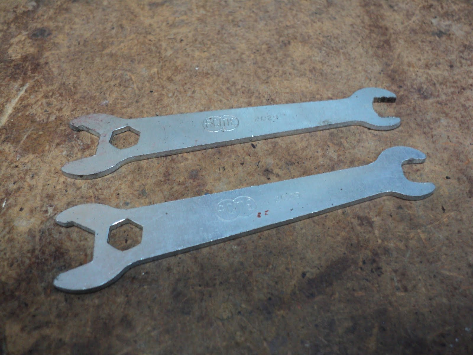 It says "Acme 2029" on them. I googled that and learned that these are for adjusting bifold door pivots.
 It must be for some big old brute of a torch. The round opening is sized to go on a 3/4" diameter nozzle -- that's much bigger than either one of my two relatively modern torches.
 On one side is embossed, "SCARFE & CO., LIMITED". On the other side is embossed, "VARNISHES, PAINTS, ENAMELS".
 And I made a chuck-based pin vise.
 Embossed on the handle is what looks vaguely like "US/C" or "USAC". Stamped at the 5/8" end is "1755", although the '1' could as easily be taken for 'L'.
 I don't know what to make of this; I'm sure he had a good reason for making it.
 I've cleaned it up; it cleaned up nicely with just lacquer thinner. On the top surface of the mouthpiece there's an etched lion and "MADE IN HONG KONG". I can't imagine my dad having had a use for this item, and neither do I have a use for it.
 Quite a nice one -- made in England; the manufacturer's name is chipped and unreadable.
 The hex is 3/4" A/F. The screwdriver tip is 3/8" wide. It's beautifully made, but there's no manufacturer's name on it. I've never seen one like it.
 It's a "274-FC GOULD IMPERIAL". Gould Imperial appears to no longer exist.
 There's no manufacturer's name, it just says "MADE IN U.S.A." on it.
 On the ferrule it says "MADE IN U.S.A."
 No, you haven't misread, and I haven't miswritten -- it's a soldering 'copper', not a soldering 'iron'; there's no 'iron' to it.
 I thought this drive square looked a bit odd. I put a caliper on it and read 9/32".


