Monday, April 28, 2014

Briggs & Stratton Model 9S502 -- Carburetor And Fuel Tank Removal


The subject engine is on a base model lawnmower, so it's a fixed-speed version -- about as simple as it gets.

The engine has seen a couple of seasons of use. It still starts and runs ok, but not perfectly to my ear. I don't like what I see when I peer into the fuel tank, so I'll get it off the engine for a thorough flush. I'd like to have a trouble-free season from the mower.

- - -

Here's a view of the fuel tank/carb/air cleaner corner of the engine.


The carburetor is a departure from what I'm accustomed to seeing on Briggs & Stratton engines -- this one has a primer bulb on it like the Tecumsehs.

- - -

Air Cleaner

A single long screw holds the air cleaner in place.


There's a ring gasket under the air cleaner's body on the carburetor's air intake horn.

Governor Linkage


There's an operator's lever that's spring-linked to the governor. I can't see that the lever does much of anything, and neither the engine manual nor the mower manual explain the thing. Other than that, the governor linkage is as one would expect -- there's a rigid link between the air vane's arm and the throttle; spring tension on the air vane's arm determines governed speed.[1]

The operator's-lever/spring-linkage affair is anchored on a bracket that's attached to the engine by two of the cylinder head's bolts. That says that the bracket is not to be disturbed.

Fuel Tank And Carburetor

The fuel tank and carburetor are removed as a unit. Proceed as follows:

1) Crankcase ventilation elbow fitting slipped off of carburetor nipple.

2) At front of fuel tank, one 1/4"-20 x 9/16" hex washerhead screw, 3/8" A/F.

3) At top of fuel tank, one 5/16"-18 x 1 3/4" hex washerhead screw, 1/2" A/F.

4) Free the governor link from the carburetor's throttle plate as you take away the unfastened unit.

The above four steps get you to here.


Carburetor Removal

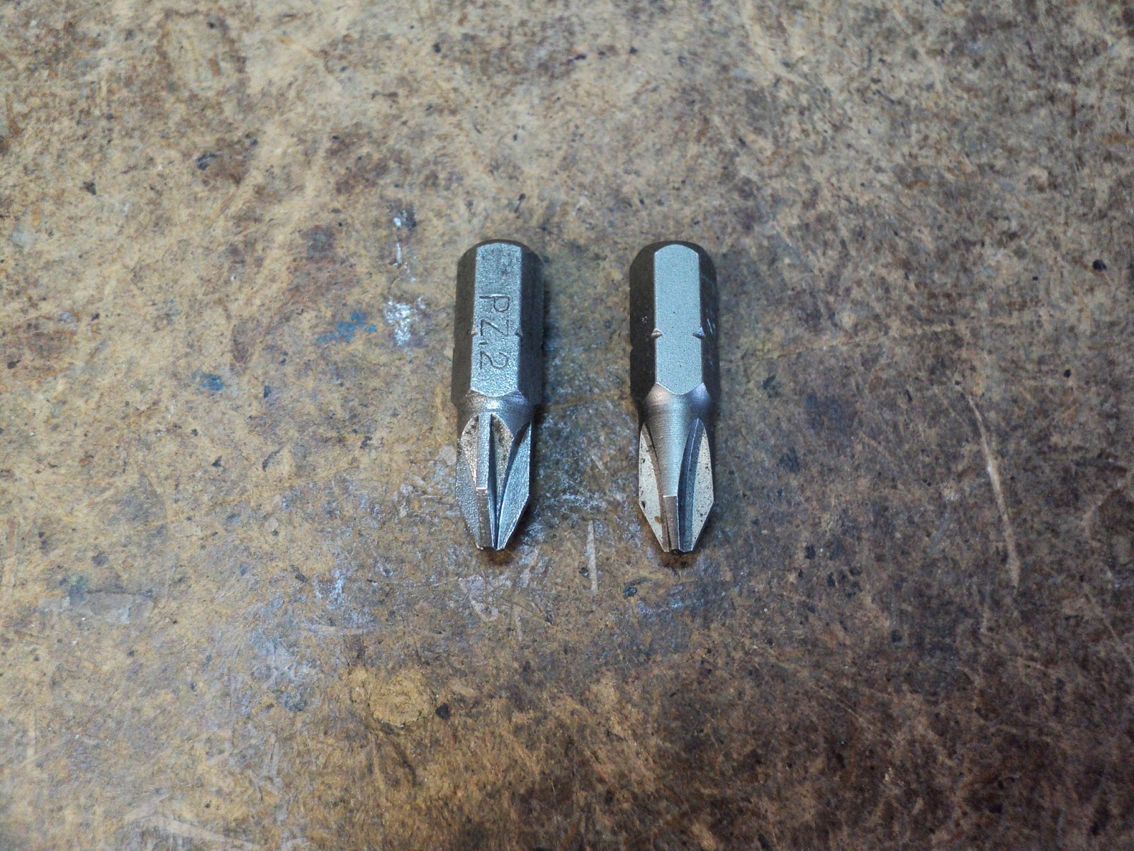
Five No. 2 Phillips recess screws fasten the carburetor to the fuel tank. (The screws are 10-32 x 9/16".)


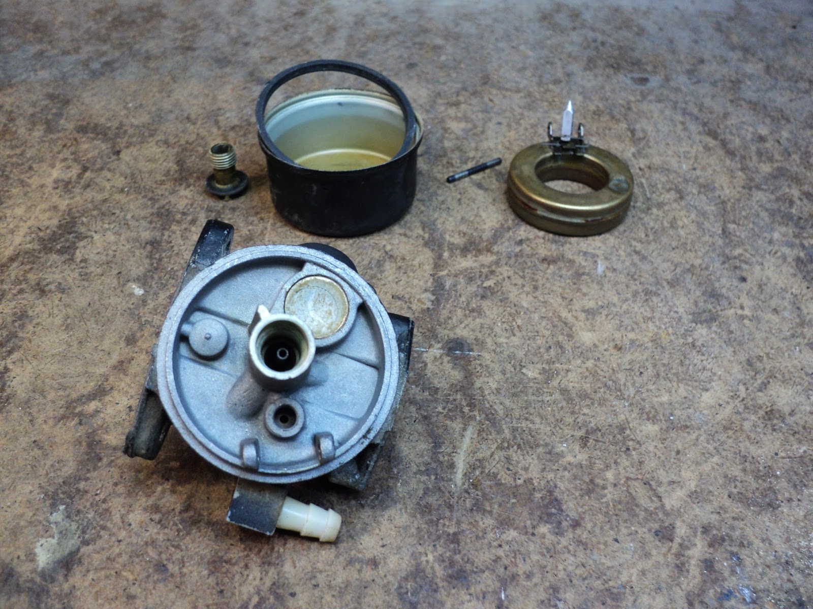
Here's a view of the carburetor off the fuel tank, after a cleaning in the parts washer.


Note the following:

- The diaphragm goes directly against the fuel tank; the gasket goes directly against the carburetor.

- The carburetor's body is entirely made of plastic.

- There's no torsion spring on the throttle butterfly.

- There's a spring in the carburetor that's free to come off its post once the diaphragm is removed.

- I haven't disturbed the primer bulb. It's probably unwise to unless a new bulb and retaining clip are on hand.

- The diaphragm is the weak point in this carburetor.[2] 'Best to have a new one on hand if you're going this far.

- There's an o-ring in the carburetor's output air horn that seals around the engine's intake tube. That seal has to be flawless for the engine to run reliably at full power. Inspect and lubricate the o-ring before re-installing the carburetor.

- - -

Notes:

[1] The governor spring's tension works to open the throttle; greater governor spring tension results in a higher governed speed.

Air vane deflection works to close the throttle; increased deflection from increasing engine speed works to return engine speed to set governed speed.

When governor spring tension and air vane deflection strike a balance, governed speed results.

[2] Diaphragms are weak points in any carburetor, for that matter. The so-called 'literature' on small engine maintenance makes much of inspecting diaphragms for punctures or tears. Nothing in an engine's normal operation is ever going to puncture or tear a diaphragm. Diaphragms do stretch and stiffen somewhat with age, though. That's what renders them marginally fit or wholly unfit for service. The symptom is simply poor/erratic engine performance. Any engine that's seen two or more seasons of use is probably due for a new diaphragm. (I'm told that using ethanol-free gasoline will greatly extend the life of diaphragms.)

Here's a view of an old diaphragm alongside a new one.


The old diaphragm is at the left. Note the stretching and stiffening in the area where the spring bears down on it. That diaphragm still works, but it's subpar.

The diaphragm in this carburetor is strictly a fuel pump and valves. The metering diaphragms in two-stroke engine carburetors are much less tolerant of stiffening; a stiffened metering diaphragm will likely render an engine inoperative with the choke off.

# # #


# # #

Saturday, April 26, 2014

Weed Eater Featherlite SST -- Zama C1U Carburetor Diaphragms Replacement


The carburetor shown here wouldn't prime at first, even though the primer bulb looked ok. Replacing the primer bulb cured that.

With the new primer bulb in it, the engine would start, but it wouldn't idle, and it wouldn't run off-choke. The next logical move was to replace the two diaphragms in the carburetor -- they're the next weakest links after the primer bulb.

- - -

Body Type And Model Number Identification

Body type and model number are crucial pieces of information when buying parts; without them, your parts dealer can't begin to help you. Even with them, there may still be a problem.

The model number on my carb didn't show up on the parts dealer's listing -- the dealer had to make a 'best guess' as to what would work for me.[1] Had I known, I would have been well advised to have the entire carburetor with me, not just the numbers.

Anyway, here's a view of the body type and model numbers on my carburetor.


"C1U" is the body type. "105H" is the model number. '105H' did not appear on the dealer's listing.

- - -

Terminology

I won't pretend that I fully understand the operation of this carburetor -- much of it is a mystery to me. What literature I've found was not much help.[2]

To simplify things, I'll refer to the 'primer-side' diaphragm for the diaphragm nearest the primer bulb, and 'main' diaphragm for the more substantial diaphragm at the opposite side of the carburetor.

- - -

Main Diaphragm And Gasket

Two M3x6mm screws fasten the main diaphragm with its cover[3] and gasket in place.


A diaphragm kit will include a new gasket. Replace both the diaphragm and its gasket.

Primer-Side Diaphragm And Gasket

Two M4x15mm screws fasten the primer body and primer-side diaphragm with its gasket in place.


A diaphragm kit may include several different versions of primer-side diaphragm and gasket. Pick out the correct ones for your carburetor and install them.

And that's about it. Reassemble everything and you should be good to go. The above routine got my Weed Eater running fine.[4]

- - -

Notes:

[1] Zama P/N GND-18 turned out to be the right part.

[2] Zama publishes a 'Technical Guide' on their website. Good luck with that. You may as well read about the care of potted plants, for all the enlightenment you'll get from the Technical Guide. Like much of 'technical writing', it's gibberish embellished with illustrations.

[3] Note the smallest of three holes in the main diaphragm's cover. That hole is there to allow atmospheric pressure to the outer side of the diaphragm. The hole mustn't get plugged up with debris -- if it does, the diaphragm won't function and the engine won't run.

[4] I suspect that most of the trouble was being caused by the old main diaphragm. There was no obvious fault in it -- no punctures or tears -- but it was not as supple as the new diaphragm; there was a perceptible degree of stiffness to it. I suppose that's all it takes for a diaphragm to lose its ability to move fuel adequately.

# # #


# # #

Weed Eater FeatherLite SST -- Zama Carburetor Removal


The carburetor is easily removed, once you know about the concealed screw.

[The following photos are of a machine that's had a fuel line modification done to it. Its external fuel lines are black and opaque; not clear like the ones the factory uses.]

Air Filter Outer Shell

This is where the concealed screw comes in. Peel back the starting instructions label a ways, and the screw is visible.


Remove the two No.2 Phillips recess screws, and the outer air filter shell; that gets you to here.


Remove the air filter element; behind it is a sheet metal support. Remove the support, noting that its convex side goes out.


There are two 55mm long screws holding the air filter's inner shell and the carburetor in place. Remove them with a 4mm hex key. Note that the upper screw has a shoulder washer and a wavy washer on it for pivoting the choke plate.


Back at the carburetor, note the locations of two tubes. Pry those off and unhook the throttle cable; the carburetor and its gasket in back are free to come off the engine.


# # #


# # #

Thursday, April 24, 2014

Vising a String Trimmer


String trimmers are awkward machines to work on. They certainly won't stand up, and they like to roll and flop around on a workbench. I came up with a crude pair of jaw-pads for my woodworking vise, and now I have a secure way to hold my string trimmer at a convenient height and orientation.

A couple of pieces of 2" x 4" would serve for this. I had some scrap, thick plywood on hand to use. Here's a view of my material on the drill press. I'm about to bore through the centre of the two pieces edge-wise, to create shaft-gripping jaw-pads for the vise. (The bore diameter will be 3/4" to fit my Weed Eater.)


Note the piece of thin material in between the two pieces of plywood. That's there to lend an 'incompleteness' to the bore, so that it will clamp down firmly on the trimmer's shaft without the jaw-pads fully closing up.

Here's the bore all the way through, after some part-way readjustment of the drill press table's height.


And here's the result. (Note that the drill bit took a path-of-least-resistance, and wandered off at a bit of an angle. For my purpose here, that's not a problem.)


Now I can try this out, like so.


Not bad for a crude prototype. The jaw-pads grip the trimmer's shaft harmlessly but firmly, and hold the machine in such a way that I can easily work on it.


There's certainly room for refinement of this idea, up to and including a purpose-made, stand-alone string trimmer vise. But what I have here so far will serve nicely for the carburetor work that this Weed Eater is due for.

# # #


# # #

Thursday, April 17, 2014

Phillips vs. Pozidriv


Posidriv is a four-flute fastener drive that's less prone to cam-out than is Phillips. Posidriv drivers and recesses look very similar to Phillips, but there is a difference, and the drivers should not be used interchangeably. Posidriv recesses are marked for identification. Pictured below are two screw heads.


The screw head at the left is Posidriv; at the right is Phillips. Note the radial strokes at the corners of the Posidriv recess. Those are there to indicate that it's a Posidriv recess.

The difference between the two drives lies in the shape of the flutes. Phillips flutes taper inwards slightly. Pozidriv flutes' opposite sides are parallel to one another. Here's a view of the two drivers.


The Pozidriv bit is the one at the left. Note how the manner in which the Pozidriv flutes are ground differs from the Phillips bit at the right. The Pozidriv flute sides are parallel; the Phillips flutes are tapered.

# # #


# # #

A Lawnmower Revivification -- Part II


* * *

[Part I of this post is here.]

* * *


The Governor/Throttle-Cable Linkage Plate

The plate is attached to the top of the intake tube with two 5/16" hex head screws. There's a throttle cable connection and a governor connection.


Here's the underside of the plate with the throttle cable disconnected.


Note the kill switch, and the governor's additional connection to the carburetor's throttle lever.

The throttle butterfly appears to be seized. This carburetor may be in rough shape.

- - -

The Carburetor Off The Engine


Note that the carburetor fastening screws are fine thread -- 1/4"-28.

- - -

The Carburetor Apart


I haven't disturbed the needle valve seat or the primer bulb -- they both look ok. The 5/16" I.D. fuel supply tube will have to be replaced.


The throttle butterfly is seized open. I wonder if that was the 'last straw' that sent this mower to the side of the road.

I'll get the throttle freed up, and the entire carburetor cleaned. I'm nearing the point where I can reassemble the engine components and try the engine out.

- - -

The Sparkplug

The spark plug is a Champion RJ19LM, 13/16" hex. It's almost immaculate; it was probably replaced shortly before the mower was junked.[1]


I just tweaked the gap a bit to give it a snug 0.030". There's no need to replace the plug that I can see.

- - -

The Chain Drive


Removing two fasteners permits the drive cover to pivot upward, affording access to the drive chain. I'll take the chain off and leave it in the parts washer for a good soak while I get the engine taken care of. Once I get the engine running, I'll attend to the rear wheel drive.

- - -

It Runs!

The engine started on the first pull; it runs nicely. Now I just have to get after the grey engine oil, the blade and the chain drive. I'll have a nice old brute of a rear wheel drive lawnmower.

- - -

The Blade

The fasteners are 1/2" and 9/16" hex. The blade fastening arrangement looks like this underneath.


(Note the 3/4" hex oil drain plug near the 'top' of the crankcase.)

The two smaller (5/16") screws came out fairly easily. The 3/8" bolt at the centre was really tight. When you run into that, brace the blade against turning with a piece of 2" x 4", like so.


That worked fine.

The blade is not in too bad condition. It's not been used to mow rocks, as some blades appear to have.


A few minutes with the belt grinder will have that back to a decent state.

- - -

Here's the blade ready to go back on the mower.


I'm not the greatest lawnmower blade sharpener on earth, and I don't try for a fine, knife-like edge. A reasonable approximation of a cutting edge is good enough for a rotary mower, and that's as much as I try to achieve.

- - -

A Slight "Whoops!"

Setting the machine on its side for blade removal did not agree with the carburetor. The carburetor drooled fuel, and the engine got flooded something awful. It might be a good practice to drain the fuel tank, and run the carburetor dry, before setting a mower on its side for blade removal.

- - -

The Roller Chain

The roller chain[2] is in pretty good condition -- entirely fit for use.


I'll get the chain back on, and tension and lubricate it. Then I can try out the rear wheel drive.

- - -

It Works!

The rear wheel drive works fine. At high engine speed, it's not leisurely -- it really moves along.

* * *

Notes:

[1] The spark plug was likely replaced for no other reason than that spark plug replacement is the done thing when an engine becomes troublesome. If I had a nickel for every needless lawnmower spark plug replacement that's ever been done, I'd make Bill Gates look like a pauper.

I can easily imagine what likely happened with this old mower -- the engine got to behaving badly, the spark plug was replaced, the engine continued to behave badly, the mower was junked. I often saw a similar routine play out at the laser printer repair outfit where I used to work. A printer would begin to misbehave, a pickup roller would be replaced, the printer would continue to misbehave, the printer would be junked.

Both little scenarios are examples of what I call 'magic bullet' thinking -- the notion that years of wear and tear on a machine can be made to evaporate by a quick, cheap fix.

Machinery seldom breaks down in simple, clear-cut ways that will respond to quick fixes. Machinery deteriorates -- over the course of long service, every bit of a machine that's prone to wear and fouling wears and fouls. The result of that is seldom outright breakdown, but rather troublesome, erratic operation. The solution is patient, knowledgeable overhaul. That's labour-intensive, hence costly, hence rejected in favour of machine replacement.

[2] The chain is 1/2" pitch. (Pitch = roller-centre to roller-centre dimension.) Apart from that, roller chain specifications can be bewildering, and I won't even try to say which chain this is, exactly. Princess Auto sells new roller chain by 10' lengths. If ever you're buying roller chain, take the old chain with you to be certain of getting the right thing.
# # #


# # #

Wednesday, April 16, 2014

A Lawnmower Revivification -- Part I


I have an old rear wheel drive lawnmower that's been languishing under a big fir tree at the bottom of the backyard for a few years. 'Time to get after it and see if I can get it working. Here's a photo of it after I hauled it up to near the patio.


The mower was a roadside find. It must be pretty old, because it lacks an engine brake. The single control bail is for the rear wheel drive engagement.

It's a Mastercraft (Canadian Tire) mower, with an MTD model number on it -- 126 283 515. That model number doesn't show up on MTD's website, so what we have here is an ancient, abandoned machine that MTD no longer recognizes the existence of. Anyway, it's too cold to work on it outside. I'll get it into the workshop and start cleaning it up; it has quite an accumulation of fir tree debris on it.

- - -

The Fuel Tank

There's the 5/16" fuel supply tube to disconnect; then, with a little coaxing, the tank just lifts off two channels at the rear of the engine's cowl. Here's a view of the cleaned up tank off the engine.


A fuel tank can never be too clean inside. I've flushed the tank with Varsol in the parts washer, then I flushed it with Fantastik and hot water in the sink, then I flushed it with methyl hydrate to help absorb and evaporate the water. I'll leave it out in the sunlight to dry out completely.

- - -

The Air Cleaner Box

The lid and air filter element are easily removed. The box is attached to the carburetor by two 1/4" hex head, 10-32 shoulder screws. There's a ring gasket that resides in a depression around the box's air outlet.


Those screws didn't come out easily. There's evidence of galling/seizing on their threads. I'll have to chase all the threads to correct that.

- - -

The Cowl And Recoil Starter

The recoil starter doesn't want to rewind itself very well.


I'll have to take the cowl/starter off and attend to that. The fasteners are 5/16" and 3/8" hex head.

I drilled off four hollow rivet heads to separate the starter from the cowl. I didn't really have to do that, but I wanted them apart so I could do a better job of cleaning the two items. I can put them back together with screws and nuts. Here's a view of the underside of the balky starter.


These starters can be disassembled by way of that shoulder screw in the centre, but beware. The screw is likely to be very tight, possibly having been installed at the factory with threadlocker. I once broke one of those screws, and had to fabricate a replacement. I'm just going to use WD-40 on this starter, and hope that that's all it will take to get it working properly -- I'd just as soon not have to dismantle the thing.

- - -

[Now that I have the cowl cleaned up, I can make out the model and serial number on the front of it. It's "TVS90 43325D SER 5350A".]

- - -

A Little Surprise

With the cowl off the engine, there appears to be nothing holding the oil filler tube in place; it just tumbles over. I whittled a cork to plug the oil filler hole for now, like so.


What I could see of the oil looked awful. It was something of a vaguely grey colour.

- - -

The Flywheel

To get the flywheel off, first brace it against turning by wedging a big screwdriver in against the flywheel's counterweight. The nut is 3/4" hex. A 1/2" square drive breaker bar works nicely.


When applying a puller, set it up so that its jaws are under the flywheel's fins. Don't apply pulling force to just the thin rim of the flywheel.


Oil the puller's screw and screw centre-point liberally, and start tightening the puller. Tighten until you meet serious resistance, then give the head of the puller's screw a whack with a steel hammer. If the flywheel doesn't break free, tighten some more and whack again. Eventually, the flywheel will let go. Be prepared for the pop and clang and clatter that you're in for. When a tensioned flywheel finally lets go, it does so quite violently. Here we are with the flywheel broken loose from the engine's crankshaft.


- - -

The Crankcase Vent

I could just leave this part be, but since I'm cleaning things up here I may as well take the vent off and clean it. Two 5/16" hex head screws hold it in place.


Inside, there's a crumbly filter element that I'd best leave alone. I'll just clean the output tube and put it back together.


And that's about far enough to go with this post. See Part II for the continuation.

# # #


# # #

MTD 12B-443F500 V-Belt Replacement


What the operator's manual for the subject machine tells you about v-belt[1] replacement is nonsense -- it can't be done that way.

Here's a view of the v-belt on the transmission's pulley.


The manual tells you to loosen off that big screw toward the lower left of the photo to release the tension on the belt. That doesn't work. The screw is not a belt-tensioning screw. (Even if it were, there isn't enough travel in the belt tensioner to ever permit the belt to be slipped off over the pulley's upper flange.)

Note the two screws[2] in the pulley's upper flange. There's a reason for those -- the screws make it possible to remove the pulley's upper flange so that the v-belt can be removed and replaced.

To get the flange off, you need a No. 2 Pozidriv[3] screwdriver and an 8mm open end wrench. (The wrench is for two ny-lock hex nuts underneath.) Here's a view of the pulley with the upper flange removed. (The rest of the pulley is pinned to the transmission's input shaft; it never needs to be disturbed.)


Now the belt can come off for replacement.

- - -

I suppose the lesson here is, "Don't be surprised when you encounter utter hogwash in a technical manual." A lot of technical instruction seems to have been written by people who've never been inside the same building with whatever they've written about.

* * *

Notes:

[1] The belt is MTD P/N 754-0637A. I'm not absolutely certain, but it looks to me like a common 3L310 v-belt. (3/8" across the wide top of the belt; 31" overall length.)

[2] The screws are M5x16mm pan head.

[3] See this post for some information on Posidriv.
# # #


# # #

Sunday, April 13, 2014

MTD 12B-443F500 Seized Front Wheels


I have an old MTD front wheel drive lawnmower that's been sitting outside idle for a few years. Its front wheels don't freewheel in either direction -- they're both quite seized. 'Time to see what's up with that.


I'll take off that 9/16" hex nut[1] in the wheel and see where that gets me.

- - -


I had to hammer the wheel off using a piece of 1" x 2" as a punch. Revealed are a splined sleeve and the drive pinion gear. Everything appears to be seized. 'Time for some WD-40 and some coaxing.

- - -


The gear and its pin came off fairly easily. The splined wheel sleeve won't budge.

- - -


An 18" pipe wrench got the splined sleeve off -- in two pieces. That's ok. The sleeve may still be salvageable. All it is is a liner for the wheel's bore, so I may still be able to reuse it.

I'll get after the right side wheel now. With both wheels off, I can check that the transmission's output shaft is free-turning. If that's ok, and it probably will be, I'll be well on my way to having this mower working as it ought to again.

- - -

The right side wheel had to be pulled with a three-jaw puller, but it came off with its splined sleeve still inside it. The right side gear also had to be pulled -- it wouldn't come off easily as the left side gear did.[2] Here's a view of the whole kit and caboodle that got the job done.


Now that the seized wheels are off, I can tell that the transmission's output drive shaft does turn, though not as freely as I'd like. The right thing to do here would be to dismantle the driveshaft's bearings and clean them properly, so I guess I'll do that.

- - -

The wheel height adjustment levers' retention is also the driveshaft bearings' retention.  A single, big snap-ring has to come off.


To get at the driveshaft's bearings, you have to remove a corner wheel-support plate at one side or the other. Two 3/8"-16 bolts and nuts hold each plate in place. Here's the left side one off the mower along with the bearing.


At this point, I can maybe pull the entire transmission and driveshaft from the right side driveshaft bearing, without dismounting the bearing itself. If I get real ambitious here, I may open up the transmission, and clean it and repack it with fresh grease.

- - -

As it turned out, the right side bearing didn't want to let go of the driveshaft easily. I took off the wheel height adjustment lever, and now I have the entire bearing/driveshaft/transmission affair off the mower.


Now I have a lot of parts cleaning to do, plus I have to deal with the broken sleeve for the left side wheel. While I'm at it, I'll take the bottom cover off the transmission, and see how its grease pack looks.

- - -

Here's a view of the underside of the transmission. It's held on with eight T20 Torx-recess screws.


The screws came out easily, but the bottom cover doesn't want to budge; I think it's stuck in place with gasket compound.

The transmission's input and output shafts feel fine as they turn, so I really have no compelling reason to open up the gearbox. I'll just let discretion be the better part of valour here, and leave the thing be. I will wire brush the ends of the driveshaft, though, where they ride in their bearings.

- - -

Reassembling A Wheel-Support Plate

This is not as easy as is getting the thing apart. The big wavy washer in between the driveshaft bearing and the plate, and the springy height adjustment lever want to prevent you from seating the snap-ring. Here's a way to go about getting the assembly back together. (It can be done either on or off the mower. I've already done the right side one on the mower. The following photos will be of the left side one off the mower.)

1) Get the assembly together with the snap-ring part-way onto the outboard hub of the bearing, like so.


2) With a big pair of Channellocks, squeeze the whole bearing/snap-ring affair together. You'll get a partial seating of the snap-ring.


3) With a pin punch, hammer the face of the snap-ring all around to fully seat it.


4) Carefully inspect the snap-ring's seating to make certain that it's correct all around -- the snap-ring's appearance can be deceptive to a casual look. Do whatever it takes with the Channellocks or the pin punch to get the snap-ring fully seated.

- - -

Dealing With The Broken Splined Sleeve

The sleeve is broken in such a way that it can be put together, and it will not collapse under an inward radial load. That is to say that it can be pressed back into place and resume doing its job, despite the awful damage that I did to it. Follow along with me here.

Here's a view of the splined sleeve in pieces.


And here it is 'assembled', and just started into its bore by hand.


Here it is in my press, being gently pressed back into its bore.


And here it is fully pressed back into place, and ready to go.


That worked out beautifully. For all practical purposes, the wheel is completely back to normal.

* * *

Notes:

[1] A Bit Of Hex Nut Lore:

The 3/8"-16 flanged hex nuts that MTD used on this machine are self-locking nuts of the 'prevailing torque' type; i.e. the nuts have been purposely distorted in manufacture so they lock onto a thread.

There are many variations of the prevailing torque principle. The nuts used here have had two opposite sides squished slightly to produce their prevailing torque effect. Here's a close-up view of one of the nuts.


Note the appearance of the upper and lower hex flats in the image. There you see the squishing that was done to give the nut its prevailing torque characteristic.

A prevailing torque nut can only be finger-tightened until the nut's distortion comes into play; from there on it has to be wrenched.

- - -

[2] Note that the two gears are different. Should you get them mixed up, it's not hard to figure out which one is which. Just study the two and consider how the driveshaft's pins must operate on them; it'll become obvious which is which.

Or, you can just look at the picture below.


The left side gear is at the left; the right side gear is at the right.

# # #


# # #