Sunday, August 28, 2011

Resizing a Furnace Filter

My wife picked up a high-end Honeywell furnace filter at a garage sale recently for two dollars. That's not a bad price considering what the things retail for[1].

There's just one little problem -- the filter is 20"x20"x1"[2], and our furnace takes 16"x20"x1"[2] filters.

Now, how hard can it be to resize one of these things? Let's see what I can do with a straightedge and a sharp utility knife.

- - -

That went fairly well. Here's a shot of the cut off end of the filter, and of how I'm trimming the glue off the end cap that I've peeled/sliced away.

The filter is well-constructed of quite tough materials, and the manufacturer didn't scrimp on glue.

What I have in mind is to reattach the end cap with hot-melt glue. I should end up with a reasonable facsimile of a 16"x20" filter.

- - -

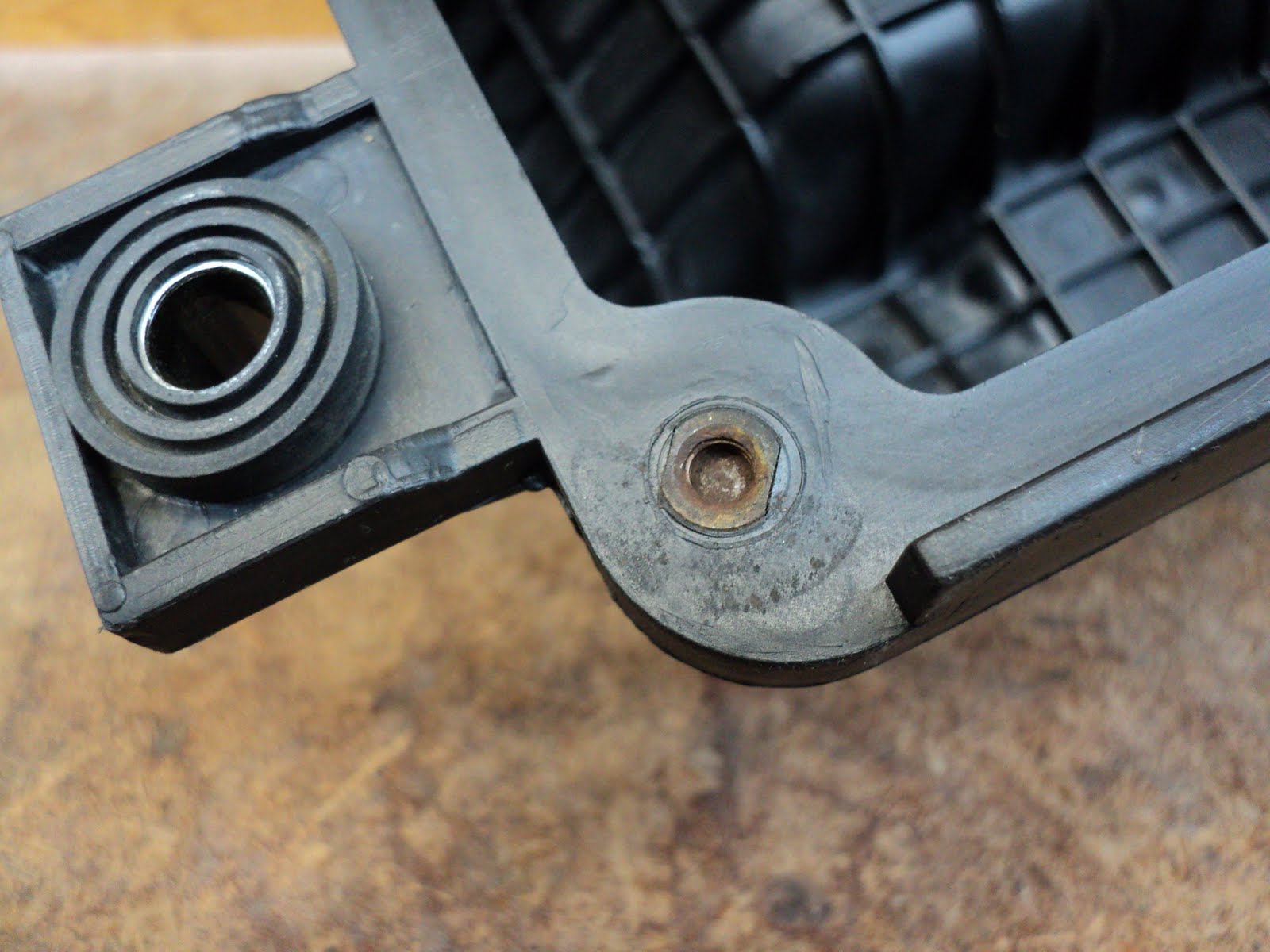
That turned out not too shabby at all. Here's a close-up view of one end of the reattached cap.


So, should you come across an oversize filter, or a whole truckload of oversize filters at a really good price, snap them up -- they're not difficult to modify to fit.

- - -

[1] I can't seem to find a price for this exact filter, but from what I've seen, the retail price of these things is outrageous.

I'll grant that they're well made of excellent materials, and I have no reason to dispute what's claimed for the things, but just how well must I be protected from every conceivable pollutant in this world to go on living in it? How did the human race ever get past cave-dwelling without Honeywell cave-fire filters to keep it healthy?

The paper wrapper that was on the filter tells me that, "This filter cleans the air of: pollen, household dust, auto emissions, mold spores, animal dander, bacteria, particles that can carry viruses [!?], smog particles." Or, to put it another way, possibly, "Be afraid! Spend lots of money on our filters and we'll protect you.

[2] The nominal dimensions of these filters are just that -- nominal; they're all made slightly undersize so they'll fit easily in their racks.

The Honeywell unit states actual dimensions of 19 5/8"x19 5/8"x13/16". The mesh filter I have is similarly undersize, though it doesn't state actual dimensions; it just gives a metric equivalent of its nominal dimensions (406mm x 508mm x 25mm).

# # #


# # #

Saturday, August 27, 2011

Noma Room Heater Model APH209W

The heater pictured below was a roadside find. It's remarkably clean, and appears to be in working order. Someone must have decided they had one heater too many, I suppose. I'll open it up for an inspection and a compressed air dust blow-out. 'Can't hurt to have a spare heater on hand.

The two feet are each attached by an M4x16mm wing screw. Removing the feet reveals a couple of truss head sheet metal screws that secure the end caps.

Then there's an M4 machine screw in each end cap's handle recess. The one at the control panel end is quite long (22mm). That's so the end of the screw reaches in to nudge the control panel's housing over as far to the right as it's supposed to sit.

The screw heads are all No. 2 Phillips recess. I quite like how this thing is constructed -- no concealed mystery clips or fastenings that you need x-ray vision to figure out. The end caps can just be pulled straight off once the screws are out.

Remove nine truss head sheet metal screws to free the rear cover, then there's a tabs/slots affair at the rear edge of the control panel. Slide the control panel to the left a bit and you can free the rear cover from the control panel's tabs.

And there we are; the unit is fully opened up. You can see in the above shot the tabs/slots I mentioned earlier.

I'll blow out what dust there is, and straighten a bent loop I see in one of the heating element's coils. The fan spins fine.

It's unlikely that you could get parts for one of these heaters. (Replacing any electrical component would necessitate cutting off 'top hat' crimp connectors and replacing them with wire nuts.) I think the idea is that if the heater fails, you toss it in the landfill and go buy a new one. That way, the poor wretches in the factory in China will have steady work. (Can you imagine assembling these things all day long every day, with a supervisor eying your 'numbers'? I'd last part of one shift before I went postal with a vengeance.)

- - -

Anyway, it's all done and back together. The two feet fit poorly. It never ceases to amaze me what shabby dimension control some mass-produced goods can exhibit. I can do better in my basement workshop.

This heater has a feature I haven't seen before on a portable electric space heater -- the fan has a separate on/off switch.

It appears you have the option of operating the unit as a silent convection heater, or as a fan-forced heater. That's a new one on me.

I'll give it a thorough trial the next time I have need of a heater, and make certain that it exhibits no bad behaviour that would account for it having been left out by the road.

Something to be mindful of on high current appliances like this heater is the molded plug right where the line cord joins it. It's normal for them to warm up there a little while operating, but if they run noticeably hot, something's wrong. Either strands of wire have broken inside the cord from flexing, or the spot-welds where the wires join the plug's prongs were poorly done. Whatever the case, no good will come of ignoring it. If the rest of the line cord is ok, cut the plug off and replace it with a screw-terminal type of plug. And then continue to be mindful of that area, and retighten the screws periodically. A 1,500 watt appliance draws a lot of current, and it needs sound, low-resistance connections to draw it through.

# # #


# # #

Saturday, August 20, 2011

Zeroing a Micrometer

Zeroing a micrometer is a pretty straightforward job but, as with everything, there are a few little wrinkles to it that the orthodox literature on the subject is unlikely to tell you about. I'll share what I've leaned about it here.

First, here's a simple illustration just for the sake of keeping our terminology straight. (Ignore the "0.462 cm" 'dimension'. That has no relevance to anything here. This was the best illustration I could find that had the correct terms on it.)

You'll often see the 'sleeve' incorrectly identified as the 'barrel'. That's misleading. The micrometer's barrel is underneath the sleeve. The barrel is rigidly attached to the frame, and has in it the female screw thread that the spindle/thimble assembly runs in.

The sleeve, as its name implies, is merely a scale-bearing covering for the barrel. And that's the key to the zeroing adjustment; the sleeve can be forced to rotate in either direction over the barrel. That's how you get the sleeve's baseline to align with the thimble's 'zero' when the spindle is fully closed down onto the anvil.

Here's a photograph of a micrometer in need of zeroing; it's off by almost a full hundredth of a millimetre.

Down in front is the little spanner that came with the micrometer for zeroing it. On the back side of the sleeve there's a hole for the spanner's hook to engage with.

In this case, I'll need to turn the sleeve so the baseline moves upward to align with the thimble's zero. What can complicate the procedure a bit is that the sleeve's friction fit may exhibit something of a 'stick/slip' characteristic -- apply enough torque to get the sleeve to rotate, and then it may 'jump' too far, spoiling the adjustment attempt. A couple of things can be done to get around that.

First off, clamp the micrometer in a vise with some stiff cardboard in place to protect the frame from being marred by the vise jaws -- a rigidly secured micrometer is much easier to deal with than one held in one's hand. The following photo shows the arrangement, along with a method for ensuring that the faces of the anvil and spindle are perfectly clean and free of debris.

A fresh cigarette paper is probably the cleanest, most lint-free thing in the known universe. Slide one between the anvil and spindle faces before proceeding, and you'll be assured a correct zeroing. (And a follow-up blast of compressed air doesn't hurt, either.)

The little adjustment spanner is awfully short; lengthen it by clamping on a small set of Vise-Grips.

The greater effective length lent to the spanner by doing this makes it much easier to get the adjustment dead on at your first go.

And here we are.

A hassle-free, perfect zeroing job.

# # #


# # #

Sunday, August 7, 2011

A Prop for a Campstove Propane Bottle

An acquaintance brought by an elderly Coleman propane camp stove the other day. The stove was in excellent working condition, but it was missing the prop to hold a propane bottle up at an angle. He asked if I could come up with a replacement prop.

The prop in the picture on the stove's cardboard box was formed from steel wire. Forming steel wire substantial enough for such a prop is a tricky business that's a lot more difficult to do well than it may look. I gave it some thought, and found a way to go about it that turned out nicely. A rummage through my stash of sheet metal turned up just the thing.

- - -

The old parking spot sign pictured below is 1/8" thick aluminum, 4" wide by 16" long. Half of it would do for a prop.

(Back in the eighties, the big corporation I was working for went on a layoff binge. I snagged R. Gibbins' discarded parking spot sign before they turfed me out too.)

I've worked with this stuff before, and it's remarkably easy to cut and file. As a layout aid, I just apply masking tape wherever I need to mark lines. A black ballpoint pen gives highly visible lines with precision that's quite adequate for this sort of work.

Here's what I came up with after a bit of fairly easy work.

And here it is doing its job.

And it fits inside the stove for transport.

# # #


# # #

Wednesday, August 3, 2011

2005 Chevy Aveo Air Filter Cover Screw Thread Repair

My son went to change the air filter on his Aveo the other day, and he ran into a spot of trouble with the cover screws. He ended up dismounting the whole air filter enclosure and bringing it to me.

The cover is fastened in place by four 10-32 x 1 1/8" screws. Two of the screws came out as they should. One screw broke off leaving its threaded portion seized in its brass threaded insert, and one screw neither broke nor came out -- it just kept turning along with its threaded insert. Here's the site of the broken-off screw. (That screw remnant got bored out -- more on that a bit later.)

The screw that just kept turning had to have its head drilled off. A 1/4" cobalt drill made short work of drilling the screw's head. The seized remainder of the screw and its threaded insert had to be torn out of the plastic filter enclosure half.

Pictured below are what's left of the drilled screw head, the screw remnant seized in its insert, the broken screw and the two good screws.

And here's what I have at the site of the torn-out threaded insert -- a big empty hole.

I'm thinking that a couple of 10-32 tee-nuts will do for getting this back in good order, with functionality no different from what it originally was.

- - -

And here are the tee-nuts ready for installation.

At the left is an unmodified tee-nut. Next to it is the nut that will go in the bored out brass insert. Its barrel will be a nice close fit; I'll just glue it in with CA adhesive. At the right is the nut for where the threaded insert is gone. I had to shorten it a bit in the lathe. While I was at it I also cut three shallow grooves in its barrel to give the epoxy I'll be using some 'tooth'.

Drilling Out the Screw Remnant

The auto makers all seem to be fond of using very hard steel fasteners everywhere. It took a 3/16" cobalt drill in the drill press to drill away the broken screw's shank. It seemed to me that the screw's shank was considerably harder than its head.

Boring the Brass Insert

The barrels of the tee-nuts have a diameter of 0.245", just shy of 1/4"(0.250"). A letter size 'D' drill is 0.246", so that will give a nice close fit suitable for CA adhesive.

Enlarging a hole in brass is actually trickier than it looks -- brass has a tendency to snag the cutting lips of a twist drill and stall it. I had to do it by small increments; 13/64", 7/32", 15/64", letter size 'D'. I countersunk the underside of the hole a little to accommodate the fillet where a tee-nut's barrel meets its flange.

- - -

The Site of the Missing Insert

Where the threaded insert tore out altogether I'll have to use epoxy as both filler and adhesive. The epoxy is unlikely to adhere well to the plastic, so I've cut a gouge in the wall of the hole with a fine Dremel burr so the epoxy can lock to it axially.

- - -

And here's the tee-nut glued in place at the site of the bored out brass insert.

That turned out very nicely.

The installation at the site of the gaping hole is going to be a bit messy. I've applied a mask there to constrain the epoxy from seeping up above the tee-nut, like so.

To prevent the epoxy from fouling the tee-nut's threads, I put a short length of 10-32 threaded rod into the nut that I had first smeared with WD-40. That was a good move, because there was no way to do the job tidily. The result is not pretty, but functionally it's fine. Here's how it looks underneath.

Topside it looks good.

So there we are. The housing's fastening arrangement is back to exactly what it was functionally -- 10-32 all around and no separate nuts to fumble with when installing the cover.

Needless to say, when my son puts it back together he's going to apply some anti-seize compound or grease to the screws' threads.

# # #


# # #

Tuesday, August 2, 2011

Mystery Fastener

Does anyone know what this is?

It was found in the street in front of my workplace. There's a bit of a back story to it that may provide a clue.

A Toronto Hydro crew had been installing a new wooden transformer pole nearby recently, to replace an elderly one that had acquired an ominous lean, so it may have something to do with hydro pole installations.

The 'pin' portion of it had evidently been cut with a bolt cutter. The pin is 9mm in diameter.

The hexagonal piece is 32 mm long overall; 17mm A/F.
It's not a threaded fastener. The pin's stub remaining in the hexagonal piece was free-turning -- there was no hint of it being threaded in. My guess was that the pin's end had a snap-ring on it that was held in a groove inside the hexagonal piece's bore.

My guess turned out to be correct.

I bored into the flat end of the hex, and I was able to drive the pin's stub out in its insertion direction with a punch and a hammer. Here's what I ended up with.

So what we have here is a very strong fastening/locking pin of some sort, that can only be undone by cutting it. It exhibits no evidence of ever having fastened anything under any sort of load. It appears to be a 'lock' with no 'key' short of a bolt cutter.

It has the numbers "42084" stamped on one flat of the hex. I've googled it every which way I could think of, and come up with nothing.

Any ideas, anyone?


# # #


# # #