Tuesday, August 2, 2016

Safe Motor Testing Gear


If you have occasion at times to bench-test fractional horsepower motors, you may find these items helpful. I wouldn't be without them.

First off is a switched outlet box with its own line cord attached. Here's a view of the one I made up for my shop.


However you go about constructing one of these, use an unambiguous toggle switch for your on/off switch, and label it unambiguously 'ON/OFF'.

I used a seven-foot, 18AWG line cord. 16AWG would have been better, but 18AWG is adequate for relatively short lengths.

Next up are some quick-connect/-disconnect motor line cords. I have four. First is one with big alligator clips on it, like so.


I didn't have clips with the correct colours of jackets on them, so I have to mind my wire colours when hooking up this cord -- not too difficult to do.

Here's a view of the cord connected to an old brute of a 1/2 hp motor.


In the example shown above, the clips and wires showed no tendency to shift about and short together, so I didn't bother with insulating tape. If a set of connections looks at all 'shaky', then by all means wrap the exposed bits with tape for safety's sake.

My second motor cord is one with two smaller alligator clips for the line connections, and a fork terminal for ground.


Third is a cord with three 1/4" spade terminals on it.


And fourth is a cord with three fork terminals on it.


Those four motor cord configurations will handle just about any motor connection scheme you're likely to run across.

The keys to safe use of the gear are these:
  • An unambiguous, unambiguously labelled on/off toggle switch; preferably one with a high operating force and an accompanying, pronounced 'click'. No mushy rocker switches or push/push switches. You don't want a switch type that might lead to an unwelcome surprise.
  • Apply insulating tape as required if there's any likelihood of connections shorting.
  • Arrange your switched outlet box and cords so they can't possibly get snagged in the works of whatever you're testing.
I find having the five above items at hand is a great time and aggravation saver.

# # #


# # #

Monday, August 1, 2016

An Antique Wagner Electric 1/2 HP Electric Motor


I picked this up from a guy on Kijiji for $20.00.


It's a bit of an antique. I didn't realize how much of an antique until I got it home, and read the I.D. label, and compared it to a modern Marathon Electric 1/2 hp motor. Here's a view of it next to the Marathon motor.


The motor is huge. The Marathon weighs about 15 lbs. The antique weighs about 45 lbs.

Here's a shot of the old motor's I.D. plate.


Following is a transcription of all the I.D. plate data:
  • REP START MOTOR
  • TYPE RPI ['might be RP1]
  • H.P. 1/2
  • R.P.M. 1725
  • CY 60
  • PH. 1
  • FRAME 67Y
  • VOLTS 110/220
  • AMPS. 7.7/3.8
  • HRS. CON 50° C
  • SPECIAL DATA [blank]
  • ORIGINAL MFR. WAGNER ELECTRIC
  • CONVERTED TO 60 CYCLES BY WAGNER ELECTRIC
  • MODEL 248R168
  • SERIAL 127
  • H.E.P.C. CODE P56 04 23-12-790 5003
Following are some notes on the above:
  • Parts of the above transcription are a little iffy. The vertical registration of the data printed on the I.D. plate's grid is poor, and some characters were difficult to be certain of.
  • "REP START" is short for 'REPULSION START'. That's something new to me, and I'll try to learn more in a practical sense. What I've seen on the internet so far looks a bit thick and dense to me.
  • Wagner Electric as an independent manufacturing entity is no more. Here's the Wikipedia entry on Wagner Electric.
  • "CONVERTED TO 60 CYCLES..." says that this was originally a 25 cycle motor, so it's very old indeed. As I recall, conversion to 60 cycles in southern Ontario, Canada occurred in about the early to mid-1950s.
Does It Run?

Yes, it does. It starts and runs quite nicely. It's currently wired for 110V operation. The wiring diagram for voltage conversion inside the connection box's cover is still in fine condition, like so.


The diagram doesn't mention reversibility, so I guess that's not doable. That's ok, though, because the motor's direction of rotation is correct for the application I have in mind. (It's CW, viewed shaft-end-on.)

The shaft has about 0.027" of end play to it, which strikes me as a tad excessive, but it doesn't appear to be a cause for concern. As the motor reaches full speed, the shaft biases itself outward, and seems to be quite happy there.

An Application

I have an ancient Sears Craftsman 8" table saw that I'd like to be rid of. I have other motors for the saw, but if this one will fit the stand I've made for the saw, it would be ideal to go with the saw. We'll see how that goes.

A Trial Fitting

Using this motor with the Craftsman saw appears to be doable.


I'll have to add new motor-mounting tee-nut locations, and possibly get a shorter v-belt, but it looks like it'll work.

I'll put a blade in the saw, clamp the motor in place, wire up the motor temporarily and try the motor under load. If that proves out, then I'll go ahead and make the adaptations to use this motor on the Craftsman saw.

It Works

I put an old thin-kerf blade in, changed the v-belt from 38" to 37", wired it up, clamped the motor in place and gave it a go. It starts up and cuts wood. So now, here's my list of things to be done:
  • Get the pulley off and clean it up, along with the motor's shaft.
  • Remount the pulley and position it closer to the motor's frame. That will minimize belt tension leverage effects on motor bearing load.
  • Establish new mounting bolt locations.
  • Install 1/4"-20 tee-nuts for the new bolt locations.
  • Reassemble everything, tension the belt, wire up the motor and cut some more wood to really give the thing a trial. Fortunately, that existing armored cable that's part of the stand will fit perfectly.
  • Put it up on Kijiji and get it out of my workshop and my life.
Pulley and Shaft

Here we are with the shaft and pulley cleaned up, and the pulley better positioned than it was.


The pulley wasn't badly seized on the shaft, but I did have to use a puller to get it off. The pulley is 5" diameter. The shaft is 5/8" diameter, with a 3/16" keyway.

The keyway had a binding spot in it that I had to file in order to obtain a free-sliding key fit. I think the binding spot was from someone once having tightened down the setscrew with no key in place.

Using the motor as its own lathe, I steel-wooled the shaft and the pulley. The outcome was reasonable. I wasn't after pristine perfection -- I just didn't want the thing to look like it had sat in a barn for the past twenty years.

I gave each bearing oil-hole six drops of 3-IN-ONE SAE 20 motor oil.

Mounting

I got the new mounting hole locations marked out, drilled, counter-bored  and fitted with 1/4"-20 tee-nuts. Here's the arrangement with the motor in place and properly bolted down.


The motor's mounting bolt slots provide a fair bit of adjustment range for belt tensioning. That's a good thing, because belt tension changes depending on the saw blade's elevation, and has to be readjusted accordingly. I've set the belt tension with the saw blade fully elevated, since that's my usual way of operating a table saw.

That saw has a tilt feature, but that will be inoperative with this motor mounting arrangement. Construction of a motor mount that would allow for saw blade tilt would involve a level of engineering skill that's frankly beyond me, so this saw is going to be strictly a 90° cutting angle affair.

Wiring

The wires that emerge from the motor are stranded, like so.


There were wire nuts on those connections that I can re-use for connecting to the incoming armored cable, but I'll want to tin those stranded wires first. When using wire nuts on stranded wire, I prefer to tin the ends of the wires.

And here we are with that done.


Four nicely tinned wire ends that won't shed strands.[1]

A Ground Connection

This motor is from back in the day when armored cable didn't include a separate, bare copper ground wire; the cable's aluminum sheath and a thin strip of aluminum were the only ground continuity guarantors.

Modern armored cable includes a bare copper ground wire, but there's no provision on the motor for connecting it. What I'll do is add a 10-32 stud to a wall of the connection box, and that will serve as a ground terminal.

- - -

And here it is.


That hex nut has an internal tooth lockwasher under it for good measure, and I scraped off paint from under screwheads as required to ensure ground continuity. The motor's frame will absolutely, positively be grounded.

Here's the armored cable installed, the ground wire connected and the line connections ready to receive their wire nuts.


Performance

With everything buttoned up, I gave the saw a brief trial.

The motor takes a full second to get up to speed, which seems a bit long to me -- I'm accustomed to seeing motors reach full speed much quicker than that. Perhaps it's a normal characteristic of a repulsion start motor.

I did a few crosscuts, and one rip cut on a short piece of 2x4, and the motor's power is impressive. I'd say that its 1/2 hp rating is a conservative one. It could probably handle a 1/8" kerf blade easily.

* * *

Update -- WEDNESDAY, JUNE 21, 2017

The saw didn't sell, so I've stashed it away against the day that I maybe enable its arbor tilt feature. We'll see.

I decided that the motor deserved to be better looking, so I tore it down and gave most of it a gloss black paint job. Following is an outline of that whole process and what it revealed of the motor's architecture.

- - -

Two 10-32 thru-bolts hold the motor together. With those removed and the motor disassembled, here's what all we have.

The Wiring-End Bell

It's a lightweight alloy casting with sleeve bearing and capped oiler. I've stripped the paint off it, and I've left it unpainted. It won't rust, and it looks fine unpainted.


Note the round screw-head in a recess at about seven o'clock. That's the head of a screw that fastens the brush carrier angular restraint prong in place for the repulsion-start commutator. More on that in a bit.

The I.D. label on the end bell is the original, from when the motor was a 25 cycles per second machine. Here's a close-up view of that.


That label is also an inspection port cover. It can be swung up for a peek at the repulsion-start commutator. I'll show that when I've got the motor reassembled.

Here's the inside of the wiring-end bell.


Note the rectangular prong sticking up alongside the bearing housing. That's the brush carrier angular restraint.

The Output-End Bell

It's a steel casting with sleeve bearing and capped oiler. I've given it a gloss black paint job.


The Frame/Stator

That got a gloss black paint job as well.


What an unwieldy thing that was to manipulate for painting preparation. Anyway, the outcome is pretty good, except for one little flaw that I'll have to touch up.

I had the frame outdoors for a spell so the sunlight and free-moving air could age the paint and harden it. When I fetched it back in, I noticed a nasty little blemish on it. It's right at the centre of the following photograph.


I have no idea what it is or where it came from -- a wee spatter of bird poop, perhaps. I suppose that's the risk you take with leaving a painted object outside for the paint to harden.

Here's a view of the end of the stator inside the frame.


The stator has a total of thirty-six poles.

The Armature/Rotor

And here we have a repulsion-start/induction-run rotor.


It has twenty poles. The commutator has thirty-nine segments. I don't pretend to understand that.

Here's a view of the rotor's other end, with the centrifugal switch flyweights.


When the flyweights trip outward at sufficient rotor speed, two things happen:
  • The brush carrier is lifted away from the commutator, so the shorting brushes are no longer riding on the commutator.
  • The rotor's segments are shorted together, so the rotor becomes a squirrel-cage rotor.
It's the first I've ever seen of such a start/run arrangement for an induction motor.

Reassembly In Progress -- FRIDAY, JUNE 23, 2017

Here we are with the output-end bell on and the rotor in place, awaiting installation of the wiring-end bell.


Note the groove in the brush carrier at six o'clock. That groove accepts the prong on the inside of the wiring-end bell that anchors the brush carrier against angular motion.

And here's the motor back together, waiting on its thru-bolts and an operational test.


I think that looks fine, with the one end bell bare metal.

- - -

All Done -- MONDAY, JUNE 26, 2017

And here we are with the motor ready to go into service.


I mean to sell it, so I've given it a temporary 18 AWG line cord that's adequate for demonstration purposes. And if I don't get a buyer, that's ok; I'll have a fine, spare 1/2 hp motor on hand that I may find a use for some day.

- - -

Sold It -- THURSDAY, JULY 6, 2017

An ad on Kijiji got results. 'Got my $50.00 asking price for it.

* * *

Note:

[1] See this post for some information on wire connection best practice.

# # #


# # #


An Ultra-Rugged Cart


This was a roadside find.


It's from two doors up the street. The house was sold, and is being renovated. All sorts of trash was out in front, along with this remarkable cart.

The thing is constructed as if for combat duty -- it looks to be indestructible (except for the plywood top). My son conjectured that it may have been originally meant for some sort of institutional application -- in a hospital, perhaps. I think that may well be correct.

The cart appears to have provision for being foldable. Right now, it's too rusted up for that feature to operate.

I'm thinking to restore it as a gardener's patio cart. The height is ideal, and I can construct a new top for it with features useful to a gardener. It will be a fine winter project.

I've Brought It Inside

Between the cart, and the old table saw next to it, I've got work for the winter lined up.


First thing is to stash that loose aluminum edging. Then I want to see how the foldability feature works. Once I have that figured out and operational, I'll delete the ruined, plywood work surface.

Foldability/Collapsibility 

A better word here than 'foldablility' might be 'collapsibility' -- I've discovered that the handles and the work surface can be removed entirely, then the frame can be folded.

Handle Removal

There's a turn-button affair at each handle that serves to retain or release a handle. Here is one in its retention position.


And in its release position.


And the handle removed.


Work Surface Removal

At the rear of the work surface there are two plunger rods. Pulling those rods outward unlatches the work surface's steel frame, and enables removal of the entire work surface, like so.


Frame Fold-Up

With the work surface removed, the cart's remaining framework can be folded very compactly.


The purpose of all that must have been compactness for storage or shipment. Once a cart had a home and a job, there'd be no more point to collapsing it.

Miscellaneous Points Of Interest

Restoring this item to something resembling pristine condition is going to be a huge job with many, many steps to be taken. For me to document it all would be too great an undertaking, and would probably lose the reader's interest in short order. But there are a number of things about this cart that I've observed that might be of interest to some readers, so I'll point them out for those who perhaps share my interest in such minutiae.

Handyman Cotter Pin Replacements

Where have I seen this sort of thing before?


Just about everywhere there was originally a proper cotter pin, that's where.

I like cotter pins, and I hate to see them replaced in the manner pictured above. Here's a brief post I wrote in 2012 about cotter pin replacement. And here's one from 2014 about a refinement to cotter pin installation that can be incorporated into new gear that one may be building.


Mystery Wheels

At the front of the work surface framework there are two small wheels (1 7/16" diameter). Here's a view of them.


And here's a close-up of one.


The wheels' purpose escapes me. I guess, when the work surface assembly is off the cart's frame, the wheels would enable one to roll the work surface assembly around like it was a wheelbarrow. That doesn't strike me as a much needed feature, but I can think of no other reason for the wheels' existence.

British Fasteners

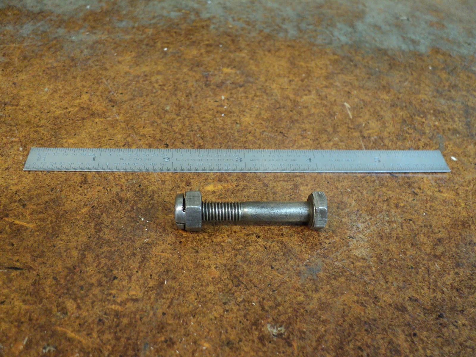
The nuts and bolts that form the axles for the above mentioned wheels have British Standard Fine (B.S.F.) threads. Here's a view of one.


That's a 1/4"-26 nut and bolt. There is no 26 threads per inch 1/4" thread in North American inch fasteners. Also, the A/F (across flats) dimension of the hexes is not 7/16", as it would be for a North American 1/4" nut and bolt -- it's slightly over 7/16", and requires a B.S.F. 1/4" wrench.

1/4"-26 fasteners are used throughout the cart. I think it's safe to conclude that the cart was made in England.

 A Paint Failure

The frame of the cart was painted a creamy white colour, and I meant to strip off what was left of that paint and repaint the frame John Deere green. My first attempt at doing the left side vertical frame member did not go well.

In my experience with chemical paint strippers, their effectiveness can vary widely. Some paint finishes prove to be impervious to the stripper, in whole or in part. (It's a curious thing, but sometimes parts of a finish will strip off readily, while other parts of the same finish will be impervious to chemical stripper. It's the same finish on the same substrate, yet it doesn't respond uniformly to paint stripper. That mystifies me.)

I've grown accustomed to encountering such behaviour from old paint finishes, and when I do encounter it I don't struggle with it -- I just paint over the parts of the old finish that resist being stripped off. My thinking there is that if the old finish is impervious to paint stripper, it should also be impervious to the solvents in fresh paint, so I can safely paint over it without risk of ill effects. Up to now, I've gotten away ok with that approach.

This time was different. Parts of the old, creamy white paint job resisted the paint stripper, but they didn't fully resist the solvents in the spray primer and paint that I applied over them. I was left with a blotchy paint job that would not dry in some places. I had no choice but to strip off my entire green paint job; what a waste of time and material.

Stripping off my paint job left me back where I'd started -- with an old paint job that resisted stripping. Instead of using spray paint again, which would have been futile, I tried using brush-on primer and paint. That worked, because brush-on primer and paint don't contain the same powerful solvents that spray paint does. Here's a view of the frame member with its first coat of John Deere green enamel on it.


(What an awkward thing to paint that is.)

It's not a great paint job. It has brush marks and a few sags, but it will have to do.

If there's a lesson to be learned here, I guess it's to do a spot check when spray painting over old finishes, before committing to the entire job. If the spot check reveals any evidence of bad behaviour from the substrate, then either strip the old finish by whatever means it takes, or try brush-on paint instead of spray. The last thing you need is to have to strip off an entire freshly applied paint job because the substrate was unsuitable.

- - -


Update -- SUNDAY, JULY 16, 2017

'Sorry. I've been remiss in keeping up this blog post.

After a great deal more work, I finally completed the cart. Here's a view of it almost a year later.


It's a far cry from what I started out with. I'm quite pleased with the outcome.

I made the new top for it from cedar fencing planks, and that's held up well so far to the elements.


So, there we are. A satisfactory rescue from landfill or the scrapyard. Instead, a useful and attractive gardener's patio cart.

# # #


# # #

Sunday, July 31, 2016

An Old Saddle Tap


This is probably not worth a salvage attempt.


This saddle tap was on some copper pipe that I picked up from the roadside while out for a walk. The copper pipe was certainly a worthwhile find, but this tap appears to be past it. I only took it off the pipe out of curiosity.

The valve stem is seized. The gland nut has been tightened down all the way, and it appears to have a crack in it, so the valve is unlikely to ever again be leak-free at the stem. But, it's not as though I have anything better to do, so let's at least examine the thing, and maybe learn something about saddle tap failure.

- - -

Here it is fully dismantled.


The gasket is a ruin -- a replacement could easily be made.

The clamp halves and the 1/4" - 20 fasteners are indestructible, and could be wire-brushed back to a decent appearance.

The valve stem and the gland nut are in rough shape; you can see the crack in the gland nut in the photograph. The valve stem's handle is not meant to be non-destructively removed from the valve stem, so that makes servicing of the valve stem and its packing a challenging proposition.

The valve seat is way down inside, and difficult to see to examine its condition, which is unlikely to be good

But just for the heck of it, I'll see if I can drill the handle off from its swage to the valve stem, and get a look at the valve stem's packing.

- - -

On second thought, maybe not. This thing is truly past it. Here's a close-up view of the valve stem portion. (I managed to get the packing washer to reveal itself.)


That packing washer is probably an item that I'll never be able to get a new replacement for, and re-using the existing one is a pretty iffy proposition.

I've spent enough time on this. I'll salvage the 1/4"-20 screws and nuts, and the saddle halves and toss the rest. Some things are just not worth pursuing.

# # #


# # #


Improving A Cheap Set of Forceps/Tweezers


Over at The Whole Garage Catalogue recently, I posted an item about a cheap pair of forceps/tweezers. Here's the post:

- - -

A Pair Of Forceps/Tweezers Of Some Sort


There's no maker's name on them, and they look cheaply constructed. The pivot is a bit sloppy, and the tips align poorly.

With a bit of work, I could improve the thing, and possibly have a useful tool for something-or-other.

I'll stash these in my spare tools drawer against the day that I feel like getting after them.

# # #


Well, I feel like getting after them. So here's what I need to do to improve this tool:
  • Strip off and possibly replace that rotten sleeving.
  • Reconstruct the sloppy pivot.
  • Align the jaws.
Sleeving

That wasn't difficult to scrape off with a utility knife. The tool is reasonably clean now.


I have some red 3/16" heat-shrink tubing on hand that might make excellent replacement sleeving. That can wait until I've dealt with the pivot and the alignment.


The Pivot

The original pivot was a 1/8" diameter rivet. I cut off its end and discarded it.

The pivot holes are slightly oversize -- that accounts for the sloppiness that I observed in the pivot's action.

I can drill out the pivot holes slightly to accommodate a 6-32 screw, but there's a caveat regarding the use of a screw as a pivot pin. It's a very poor practice to have a pivot point operate on a screw thread. You want a pivot point to operate on a full rod/cylinder. So, what I need here is a 6-32 screw that has an unthreaded shank portion that's just the right length to serve as the pivot point, while providing thread enough to be fastened by a Nyloc nut.

I have some 1 3/8" long 6-32 hex socket head cap screws with unthreaded shank portions to them, but the unthreaded portions are too long. So, I threaded one of the screws further, and now I have a screw that should serve nicely as a pivot (once I've cut it down to correct overall length). Here's a view of the screws I've just been on about.


At the left is an unmodified screw. At the right is a screw that I've threaded further. That one's going to be my pivot screw.

The pivot holes need to be enlarged slightly to accept a 6-32 screw, and it's important that I get as close a fit as possible so as to minimize slop in the pivot. Consequently, I didn't just go with the conventional 6-32 clearance drill size of 9/64". I miked the screw's shank, and chose a drill size based on that result.

The screw's shank measured 0.135". The closest clearance drill size is No. 29 (0.136"). So I went with a No. 29 drill, and that gave me just the outcome I was after -- a relatively slop-free pivot. Here's a view of it assembled without a nut.


Now I just have to cut the screw down to correct length, add a Nyloc nut, and my improved pivot will be done.

- - -

And here we are.


A slop-free, reasonably tidy pivot.

All that's left is to lubricate the pivot, align the jaws and add new sleeving.

- - -

Done.


I've got a decent set of forceps/tweezers from what was a piece of offshore junk. Very satisfying.

# # #


# # #


Friday, July 29, 2016

Material Is Where You Find It


A house painting outfit came by a while ago and asked my wife if they could plant a promotional sign on our front lawn. They were doing that all over the neighbourhood. My wife let them, and the sign stayed for days. The painting outfit never came back to retrieve the sign, and I finally pulled it up and stashed it under the carport. Today it occurred to me to dispose of the thing. Here's a view of the sign.


It's a 32" x 20" plastic sleeve affair draped over a skinny steel rod frame. Take away the plastic sign and here's what's left.


About 90 linear inches of 4.5mm diameter steel rod (about 23/128" -- just shy of 3/16").[1]

It's a bit of an odd diameter, but I might find use for it for something-or-other. The price was certainly right.

- - -

Note:

[1] It's undersize for threading 10-24 or 10-32, though I've half a mind to try it and see if I still get a useable result.

# # #


# # #