Sunday, November 24, 2013

A Cummins Fixmaster 1/4" Drill Teardown


[NOTE: This post got truncated by a Blogger mishap, and I didn't have it in me to try to recreate the lost material. The information here is sound as far as it goes.]


I brought this over from the garage. I thought I'd tear it down and clean it up and pack the gearbox with fresh grease. When I'm done, I'll make a place for it in the workshop where it can be at-the-ready. If nothing else, I'll have a very nice drill handy for light work. Here goes.

1) The Brushes

A neat feature of this drill is the externally accessible brushes. And they don't look too far gone at all.


2) The Handle Left Side Cover


- Remove the two small screws that secure the slide switch. NOTE that these screws are an uncommon size; I think they're 3-48 -- not a likely hardware store item. Should they ever be lost, you'd probably have to drill and tap the switch frame to accept 4-40 screws.
- Two 8-32 x 5/8" oval head threading screws.
- There's a little triangular projection near the top front of the handle cover that makes removing the cover a bit of a 'wiggle-and-jiggle' exercise.
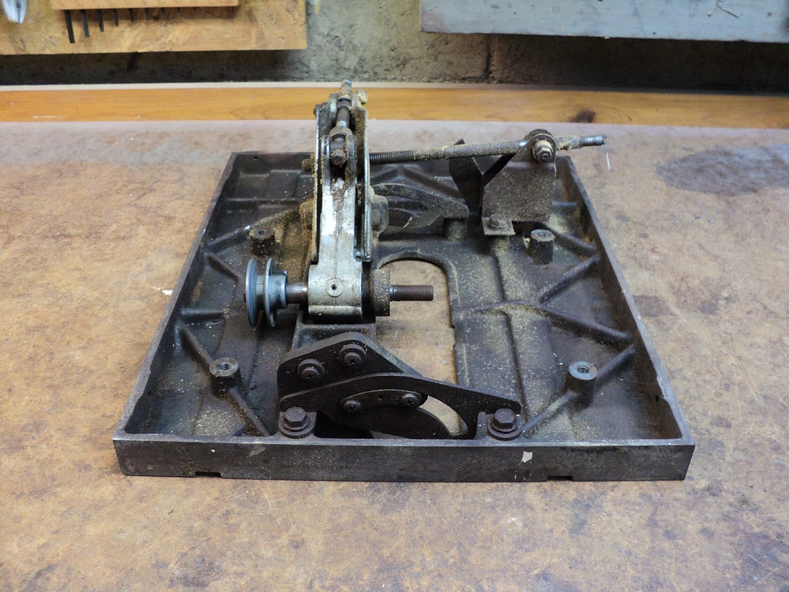
3) Gearbox

- Two 10-24 x 3" plain slot filister head screws.
- NOTE the thrust washer that's loose on the motor's output shaft at this point.
- NOTE that the circular I.D. plate can come away now.


This is a drill gearbox architecture I've not seen before -- there's a plate enclosing the reduction gearing chamber that carries the front motor bearing

4) The Chuck

The chuck is a wonder. It's tightened by means of a cam that you turn with a 5/32" hex key. Here's a view of the chuck taken apart.


The cam is that shouldered pin affair at the lower left of the photo. Note the barely visible dot on its end, and the red dot on the base of the chuck. On the base of the chuck it says, "ALIGN DOTS. ADJUST SLEEVE. LOCK WITH KEY."

Aligning the dots sets the cam to where it least extends that round plunger to the right of the chuck's base. At that point, you  snug up the chuck's sleeve by hand, then you turn the key in the cam to force the plunger up against the ends of the chuck's jaws. That's the action that securely tightens the chuck.

* * *

ARRGGGHHHHH!!!!! BLOGGER WIPED OUT A MAJOR UPDATE HERE.

 I'm not even going to try to re-create it. 'Sorry, but I'm going to truncate this post and call it a loss.

- - -

Anyway, I did carry on and complete the cleanup and re-lubrication of the drill, plus I replaced its shabby power plug. It runs beautifully.

I also modified the chuck key for better comfort and leverage, and added a chuck key leash per my usual method. Here's a view of the drill with its chuck key leash.


Now I have a portable drill that's about the same age as I am. (From what I can find, these date from the early 1950s; I was born in '51.)

# # #

FEEDBACK

# # #


A Sears Craftsman Model No. 103.24241 8" Table Saw


I was given this saw by my former employer. I believe the saw had belonged to his elderly father, who no longer had use for it.

The saw's innards appear to be in fairly good condition. There was no mitre gauge with it; I'll have to come up with a replacement. This could be a pretty decent little saw given some TLC.

The base has been brush-painted. Whoever did it did a remarkably good job of it, but it's still a brush paint job on a piece of machinery -- yuck. That's just begging to be stripped and redone properly.

- - -

Teardown -- TUESDAY, NOVEMBER 26, 2013

1) Rip Fence

The rip fence registers to its rail at the front, and locks to the front rail, like so.


That circular part at the centre of the photograph is the clamping element. Lowering the fence's lock lever fully pulls the clamp up snugly against the rail. The fence lock also squeezes the rear edge of the table. (I'll show that when I get to the final rip fence alignment adjustment.)

When unlocked, the rip fence lifts away easily.

2) Table Insert

The table insert has leaf spring clips fore and aft that hold it in place. A finger tug is sufficient to pop it out.

3) Blade

The arbour is 1/2" diameter, so the blade nut is 3/4" A/F.

The blade nut on this saw was on tight. I had to block the blade with a wrench handle, and use a big wrench on it, like so.


With the nut off, there's a single clamp washer to remove, then the blade comes out.


4) Rip Fence Rail

- Three 10-24 x 5/8" filister head screws.


5) Elevation And Tilt Handwheels

- One 10-24 x 1/4" cup point set screw per handwheel. (3/32" hex socket.)


- NOTE the notch in the end of the elevation spindle. A projection in the hub of the handwheel engages that notch when the handwheel is fully, correctly in place. The tilt handwheel on the right side of the saw is identical to the one shown above.

6) Tilt Scale Pointer

- One 8-32 x 3/16" round head plain slot screw.

7) Saw Base/Table Separation

- Four 5/16"-18 x 1/2" hex washerhead screws w/captive toothed lockwashers.


(That pulley looks to me like it's way too far over to the left.)

- With the fasteners removed, it's just possible to get the sheet metal base away from the table/mechanism. The base has enough 'give' to it that you can force it over the end of the elevation spindle, and so free it.

8) Labels

They're fastened with hollow rivets. Drill/chisel them A/R from inside to remove them. Here's a view of the three of them.


The model number label is from the lower rear of the saw's base.

With those labels off, I can see the original colour of the base; it's a blue/grey that probably looked pretty good. Why this saw was given a cheesy aluminum paint job is beyond me.

- - -


The Table/Mechanism

Following is a sequence of four reference views of the table/mechanism while it's all still together.


Altogether, there are seven 5/16"-18 x 1/2" hex washerhead screws w/captive toothed lockwashers holding the mechanism to the table. Here's the plan: a) Separate the mechanism from the table. b) Clean the male and female threads of the elevation and tilt screws. Blow/brush the dust off the rest of the mechanism. There's really nothing to be gained by fully dismantling the mechanism; I could just make trouble for myself were I to do that. The arbour's bearings feel ok, so i'll just leave them be as well. The pulley needs to be repositioned further inboard -- that's no big deal. c) Deal with the table's rust and get it back to decent condition. I have a suitable length of steel flat that I can use for a mitre gauge bar. I'll have to ensure that it's able to run freely in the slots. d) Reassemble the whole works.

- - -

Continued here.

# # #


# # #

Thursday, November 21, 2013

A Pants Hanger Gone South


Nothing is really 'broken', it's just that the prongs of the hook/clamp affair came out of one of the hardwood jaws.

I'll put it back together with CA adhesive, but I'll add a little touch that will make the glue-join even more secure. I'll file a few shallow notches in the prongs, to give the adhesive some 'tooth', like so.


Here's the hanger reassembled with CA adhesive.


That should stay together approximately forever.

# # #


# # #

P205/75R14 Spare Tire -- 1999 Ford Ranger


Back when I bought my '99 Ford Ranger new, I got the base offering -- no optional extras whatsoever aside from the long box. I thought, "There. I've got one of the commonest, easiest-to-maintain vehicles on earth. What can go wrong?"

Well, what went wrong is that 14" wheel rims became obsolete. You may as well go shopping for new wheels for your Roman chariot as try to obtain a replacement for a 14" rim on a Ranger; 14" rims cannot be had, except for the odd one on Ebay.

"Why do you need a wheel rim?", you may be wondering. I need a wheel rim because the spare tire's rim is a rusted ruin. The Ranger's spare tire lives outside beneath the box. After a decade of that treatment, the rim looks like something that's spent a decade under a pickup truck's box, in a climate that features salty slush on the roads for a good part of each year. Here's a view of what I'm left with.


Air-tightness at the tire's beads is not on; the thing had multiple bead leaks on both sides.

The least costly solution I can think of is to install an inner tube -- those can still be had; my son is getting me one from an internet outlet in the U.S.A.. We'll see how this goes.

I'll update this post as I go along.

- - -

It's Here -- MONDAY, DECEMBER 9, 2013

The inner tube finally arrived -- standard parcel mail service across the border takes its own sweet time

Anyway, the tube came folded up in a USPS 'PRIORITY MAIL' box -- there was no manufacturer's packaging. On the tube is printed,

"AUTO BUTYL TUBE
GATEWAY
GR-13/14/15
TR13
MADE IN KOREA"

The tube looks to be quite substantial; it looks like it ought to hold air.

I take it that the "GR-13/14/15" indicates that the tube will fit 13, 14 or 15 inch tires -- it's quite the versatile item.

Later today I'll take it to Dan's garage, along with the tire and rim, for them to install the tube. We'll see how this goes.

- - -

All Done

The tube fits and works. Yeehah!

# # #

FEEDBACK

# # #

Saturday, October 19, 2013

A Broken Wing Screw


I went to take a photograph of something on my workbench with the aid of my mini-tripod, and something didn't feel quite right as I tightened the little wing screw that secures the head of the tripod. It turns out there was a good reason for that.


The plastic wing affair broke. Here's a view of the screw removed and on its own.


Piece of junk.

I'll have to get the remnants of the wing off the screw however I can, and see if I have a wing nut that will fit that I can glue on for a replacement wing.

- - -

Here's a method for clamping a screw thread in a vise without marring the thread.


Cut through one side of a hex nut, and use that as a primitive 'collet' to grip the thread in a vise, like so.


Now I can get pliers onto that wing remnant and crank it off the screw.

- - -

That worked fine, but my 'collet' didn't want to unscrew easily after having been clamped onto the screw in the vise. I hammered a chisel tip into its saw cut gently to persuade it to open up a bit, and it unscrewed. The chisel's tip never reached the screw's thread, so no harm was done.

- - -

I happen to have exactly one M5 wing nut in my stash of M5 stuff. Here, I've attached it to the screw using CA adhesive as a threadlocker.


Back in business.

# # #


# # #

Recapping Tubes Of Sealants


Don't let this happen to you.


That's what happens when you over tighten a tube's cap. It's not helpful.

The temptation to over tighten is great; after all, you don't want the material to harden in the tube. Resist the temptation, though. Just snug down the cap and leave it at that. Further tightening past the point of closure only leads to the pictured result.

# # #


# # #

Tuesday, October 8, 2013

Ryobi 10" Table Saw (BTS12S) -- Tilt ('Bevel') Mechanism


I was given a broken down old BTS12S that I've been restoring to working order. I've got the saw running, but there's a curious problem with the 'bevel'/tilt[1] mechanism. Permit me to back up a little, and describe the whole elevation/tilt operation of the machine.

On the BTS12S, a single handwheel operates both blade elevation and blade tilt. The default position of the handwheel is for it to engage the elevation screw. Pushing the handwheel in against a spring disengages it from the elevation screw, and engages a rack-and-pinion gear set that operates the tilt function. The problem I have with the machine is that the rack-and-pinion gear teeth barely engage one another deeply enough to work -- the teeth mostly just skip to no effect. I can see no adjustment to improve the gear teeth engagement. Here's a view of what I've just been on about.


Everything about the mechanism appears to be factory-issue, which says that the tilt function on this saw has never worked, right from day one. That likely wouldn't have mattered to the guy who gave me the saw, because he was only using the saw to cut up shipping pallets into firewood. Regardless, whether I keep this saw or give it to someone, I'd like for the tilt function to work as it ought to.

From what I can see so far, it looks to me like the elevation screw emerges at the front of the saw too low down for the rack-and-pinion gear set to ever engage properly. I need to see if there's a way I can alter that, without fouling up the elevation function.

- - -

Here's a view of the front of the saw upside down with the handwheel and elevation screw removed.


Note the position of the large washer just inside the tilt slot where the elevation screw emerges -- it's not centred, it's almost as far away as possible from the rack. It's beginning to look to me like Ryobi got a dimension wrong, and may have made many of these saws with this same defect.

I've removed the washers and spring that are immediately behind the tilt slot, to get a direct view of the hole in the tilt carriage that the elevation screw emerges from. Here's a shot of that.


The photograph shows it poorly because of a shadow, but that hole is way too far from the rack for the elevation handwheel's pinion to ever engage the rack fully.

I'll try elongating that hole in the direction of the rack, so that the elevation screw can be manually forced toward the rack when the tilt function is engaged.

- - -

Well, the job I did of elongating the hole with a hand grinder is not pretty, but it did yield the outcome I was after; it's now possible to force the rack-and-pinion to engage fully. The tilt function is operable throughout its entire range.

Conclusion

I'm normally disinclined to condemn a piece of engineering, I know that there are many compromises that must be made, but for this tilt mechanism I'll go right ahead and condemn. The tilt mechanism is, in a word, shabby. It never should have left the factory. What respect I ever may have had for Ryobi has taken a nosedive with this little exercise. I consider such marginality in a mass-produced, low tech piece of gear to be inexcusable.

If you're shopping for a legitimate woodworking machine for cabinet making and the like, steer clear. If you're looking for a firewood cutter, the Ryobi will serve. That's the class it's in, after all.

- - -

Note:

[1] Ryobi insists on referring to 'tilt' as 'bevel'. Tilt and bevel are not the same thing; bevel is an effect, tilt is a cause. Setting the blade's angle to something other than ninety degrees via the tilt mechanism bevels nothing -- it merely tilts the blade. Cutting wood with the blade tilted results in a bevel.

It appears that Ryobi's grasp of English is as marginal as its tilt mechanism.

# # #


# # #