Saturday, February 9, 2019

A Compact, Lighted Travel Makeup Mirror


A neat little item, but this mirror's lighting is flaky.


The unit is six inches square.It has a light with selectable colour filtering at either side of the mirror. The lights come and go at random. Let's see if we can discover the fault.

- - -

The lighting is from two little incandescent bulbs powered by four 'AA' cells.[1] Here's a view of the lights popped out of the mirror's frame for access.


The bulbs weren't firmly screwed in. Snugging them up tightly did away with the flakiness. The mirror's lighting now works as it should.

As for any further seviceablity of such a thing -- good luck. Should a cold solder joint surface inside, it would be game over because I can see no way to non-destructively dismantle the mirror. It looks to me like the factory screwed the front frame to the rear frame, then forcibly snapped the mirror in place over the screw heads. 'Odds of prying out the mirror without breaking it are slim to nil.

- - -

The Light Bulbs

They're what's known as G-3½ miniature screw base bulbs. They have their electrical characteristics printed on their bases, but there are no type numbers. (They're rated at 4.8V, 0.5A.)

The 'G-3½' business breaks down like this:
  • G = Globular (as far as I know) bulb shape.
  • 3½ = 3½ eighths of an inch bulb diameter; i.e seven-sixteenths of an inch.
You can see what an arcane bit of business we're dealing with here.

I have an extensive listing of miniature light bulb types in my possession, in the form of an elderly Electrosonic Inc. catalogue. Nowhere in that catalogue's listings is there a G-3½ bulb rated at 4.8V, 0.5A. The odds of finding such bulbs are slim to nil.

- - -

So there we are -- a nicely designed and executed little makeup mirror that will be landfill should it ever give more trouble than it has so far.

* * *

Note:

[1] The mirror is fitted with a 3.5mm phone jack for use with a six volt AC adapter. Plugging in a plug disconnects the battery, and puts the unit on external power.

# # #


# # #

Monday, February 4, 2019

A Zenith Royal 66 AM Receiver


Here's an antique from the earliest days of the transistor radio.


It's so old, it has a bulky air-dielectric tuning capacitor in it, rather than a modern, miniature film-dielectric tuning capacitor. Here's a rear view of its innards.


It's quite dead. I'll check the battery cells and their contacts.

- - -

All four cells were totally discharged. The unit must have been left turned on and neglected. New cells got it going, and it works nicely. The volume control is noiseless. There's a bit of noise at the very low end of the tuner's reach.

The battery compartment contacts are excellent -- clean and free of oxidation. Zenith knew what they were doing.

 The only real flaw was a loose tuning dial numbers ring. Some CA adhesive took care of that.

- - -

It Was A Different Time

The battery compartment map on the inside of the rear cover gives instruction for the installation of mercury cells.


Mercury cells have been virtually banned for a long time now, because of their toxic contents.

- - -

So there we are -- a working radio set, probably from the 1950s, back when we used to manufacture consumer goods in North America.

# # #


# # #

Sunday, February 3, 2019

A Lawn-Boy ST320E Snow Thrower


Here's a 'won't start' snow thrower that my son picked up for very little money.


I just brought it in from outside, so there's snow on it. I'll leave it to make a puddle on the floor, and return to it when all is dry.

- - -

It's a Model No. 55380, Serial No. 000242. That serial number doesn't show up on Lawn-Boy's website as being legitimate. Perhaps it's a Canadian serial number that Lawn-Boy couldn't be bothered to track.

Anyway, I got some useful information from the website on the model series:
  • Swath: 20 inches.
  • Engine: Tecumseh Model No. AH600-1657N; 3 hp; 2-stroke cycle; electric start.
  • Engine Speed: 4,000 rpm ± 100 rpm..
  • Ignition Coil Air Gap: 0.013".
  • Mix Ratio: 50:1; originally 32:1. [The subject machine is 32:1.]
  • Spark Plug: Champion CJ8Y.
  • Spark Plug Gap: 0.030".
So there are the fundamentals. 'Next step is to see if the engine has spark and, if so, does the kill switch work.

- - -

Top Cover Removal

Seven No. 10 x 1/2" hex washerhead screws (5/16" A/F) fasten the top cover. (Two of the screws are missing on this machine.) The fuel tank's cap must come off, then the cover can be forced up over the fuel tank's neck and slid up the handlebars a ways. A small bungee cord serves to hold the cover up out of the way.


Spark Plug Access

Here's where things get a bit messy. I don't have a compact 3/4" spark plug socket that will reach in neatly under the machine's rear cover, so I'll have to loosen off the rear cover a bit to get the spark plug out. A few more No. 10 x 1/2" hex washerhead screws have to come out.

And here's the spark plug out.


It's a resistance-type spark plug -- Champion RCJ8Y. Centre electrode resistance is about 13k ohms. The plug is in reasonably good condition. Gap is a 'loose' 0.030".

And a test shows that I have spark, and the kill switch works. I'll clean and gap the spark plug and reinstall it.

- - -

A Needless Retaining Clip To Watch Out For

Tecumseh likes to install a barb-fastened retaining clip on a cooling fin of the cylinder head to keep the spark plug wire in place. On this engine, the clip has come part way off. (The clip is right at the centre of the following photograph.)


Delete the clip entirely; it's not needed, and it can come loose and get into the engine's flywheel/starter-gear area. I've had that happen on an MTD snow thrower with much the same engine. The little gone-astray clip had the engine jammed solid until I found and removed it. Here's a view of the clip from this engine, alongside the one that I had once retrieved from a similar Tecumseh engine.


Again, the clip is not needed, and can cause nasty trouble if it comes loose.

- - -

It Starts!

At room temperature here in the workshop, it started on the first pull with only choking -- no priming. I know from experience with this engine that it is very easily flooded by needless priming. I wonder if that might have been a factor in the original owner's decision to let the machine go -- perhaps he'd been inadvertently flooding the engine. There's a chart decal[1] on the dashboard, though, that gives good guidance for use of the primer bulb. What all went on with the machine before my son got it, I'll never know.

- - -

Rear/Underside Accessibility

Rear/underside service accessibility on this machine is dreadful. There's a single rear/underside cover that incorporates the dashboard. Gaining access to the carburetor to remove and service it looks like a daunting task. Here are two views.


Note that someone has cut away the grillwork under the carburetor to lend accessibility to the carburetor's float bowl. I'll remove the float bowl and take a look-see for contamination.

- - -

There's some particulate matter in the float bowl, but no evidence of water. The float level appears to be set very high.

Be that as it may, for the time being I'll go with the adage, "If it ain't broke, don't fix it.", clean the float bowl and put it back on. There are some improvements I want to make to a couple of cover attachment points.

- - -

Two Cover Attachment Brackets Riveted So They Can't Swivel

The Tinnerman nut brackets for attaching the top cover at its upper rear corners tended to swivel a bit, so the nuts would fail to align with the screw holes in the cover. I gave each bracket a 1/8" hollow rivet, and that's the end of that little problem.


Electric Starter Switch

Dismounting the electric starter switch is the key to removing the rear/underside cover. (Along with removing the wheels.) With the switch off its mounting block, and the mounting block off the cover, the switch can be passed up through a big opening, out of the way of cover removal. Here's a view of that.


Wheel and axle removal is straightforward -- there are external snap rings holding the wheels on.


And here we are with the rear/underside cover out of the way of carburetor removal.


In addition to getting the starter switch and its mounting block and the wheels out of the way, the following items must be dealt with:
  • The discharge chute's positioning crank must be unpinned and removed from its shaft.
  • The kill switch's wiring must be disconnected from the kill switch.
  • The choke handle must be forced through its grille opening.
  • The primer tube must be removed from its nipple at the carburetor.
With all that done, the starter cord can be eased out a bit, and the cover moved well aside.

- - -

Carburetor Removal

Here's the carburetor accessible for removal.


And here's the carburetor off the engine.


Note the following:
  • A spring-type hose clamp secures the 1/4" I.D. fuel line to its nipple. Have a suitable container handy to drain the fuel tank, or a stopper for the end of the fuel line.
  • Two 3/8" A/F hex nuts fasten the carburetor to the engine.
  • There's a gasket, and then a spacer/insulator block between the carburetor and the engine. The gasket is likely to be welded to the carburetor. Just leave it be. Leave the spacer/insulator block on the engine.
  • There are no extraneous mystery holes for the governor spring and link. Governor spring and link installation is straightforward.
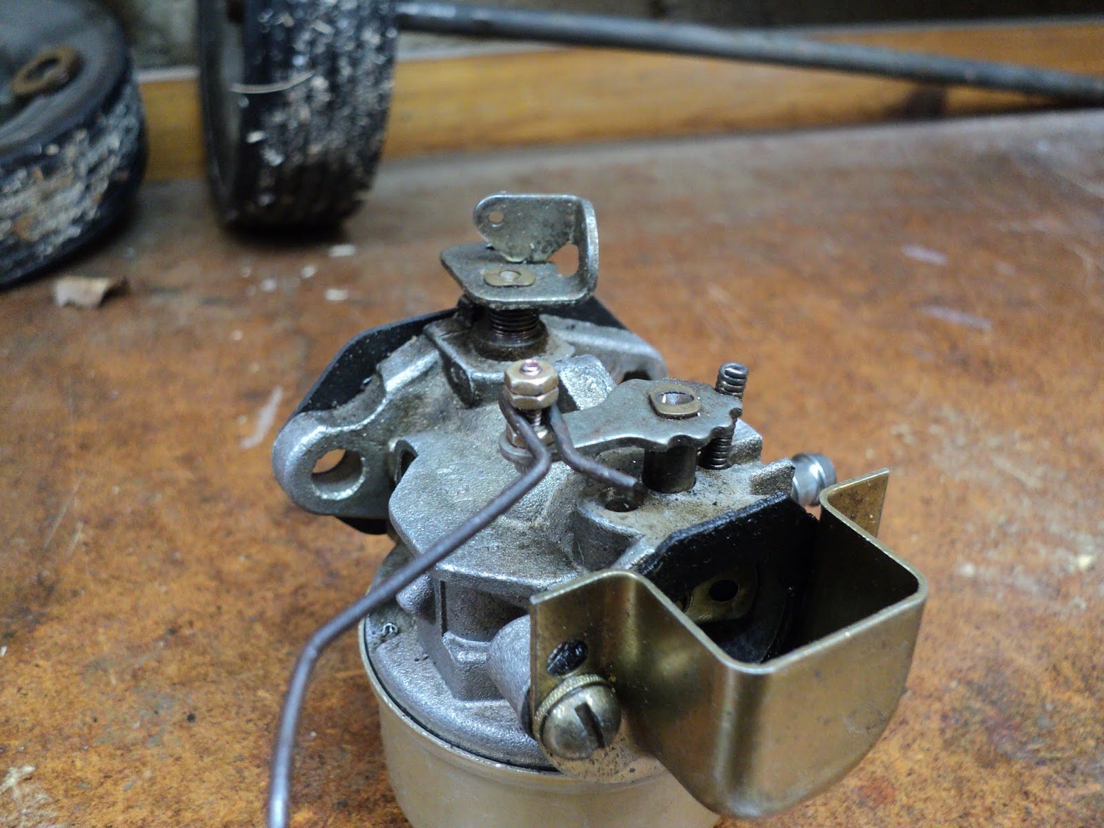
  • The carburetor is as simple as carburetors ever get. There is no idle circuit -- the carburetor is designed to operate only at the engine's 4,000 rpm governed speed via the main jet. There is no mixture adjustment.
  • The choke detenting on my carburetor is imperfect; the choke butterfly's lever doesn't want to engage the fully wide open detent. The choke butterfly's wide open position is a little askew from fully wide open. I can see no way to correct the flaw.
- - -

Fuel Tank Removal

I chose to remove the fuel tank so I could thoroughly drain it and dry it out. The tank is attached at two points, with one 1/4"-20 fastener and one 10-24 fastener. The nuts used are prevailing-torque types, so they're a bit stiff to get off and on.
- - -

A Brief Trial -- MONDAY, FEBRUARY 4, 2019

I buttoned up the machine sufficiently to try it out, mixed up a half litre of 32:1 fuel and took it outside. It started on the first pull. It's been mild lately, and the snow has compacted and gained density, so it wasn't much of a trial. But the machine does work. 'Time to finish up 'perfecting' it.

- - -

Remounting The Electric Start Switch Mounting Block And Switch

The original fasteners were discrete screws and nuts. I prefer not having to deal with discrete nuts, so I'll install threaded inserts. We'll see how that works out.

- - -

And here we are with two 6-32 inserts in the mounting block.


And three 10-24 inserts in the underside cover.


I add a bead of runny CA adhesive around the flanges of threaded inserts, just for good measure.

I'll reinstall the mounting block and switch with anti-seize compound on the screw threads, and I can get on with an examination of the snow thrower's drive train.

- - -

Drive Train Cover Trouble

The two lowermost screws for attaching the cover are not original -- they're 10-24 screw-and-nut arrangements that have rusted to near seizure. I managed to get them apart and out. Here's a view of the cover fastener complemement.


The best I'll be able to do will be to come up with hex head replacements for the 10-24 screws. New nuts and anti-seize compound should make for an assembly that can be opened up again readily if and when the time comes.

- - -

The V-Belt Drive Train

It appears to be in remarkably good condition.


The belt looks ok. The tension idler runs on a big sleeve bearing that's in fine condition. I can button that up, and put the machine outside to see how well it starts at low temperatures.

- - -

Whoops! -- THURSDAY, FEBRUARY 7, 2019

There's nothing like old machinery to keep one occupied. I was trying out the machine this afternoon, and it started to run poorly after a bit. It turned out that the choke handle's stud had popped loose from the choke lever. The engine must have remained choked after I thought I'd opened the choke.


Not one of Tecumseh's finer moments.There are three possible ways to go to repair this:

a) Swage the stud back in place in its lever with a centre punch. That might work, but if the stud worked loose once, it may work loose again. The design is evidently not trustworthy.

b) Cut away the grillwork in the cover immediately behind the carburetor, so one can reach in and operate the choke lever directly, without the aid of a handle. That would do away with the possibility of another choke handle failure, but it's an inelegant solution -- the sort of thing a bush mechanic would do in a pinch. I'll leave that for a last-ditch solution.

c) Fabricate a new stud from a 2-56 screw and hex nuts and red threadlocker. I have some stainless steel 2-56 screws on hand that I got from Amazon a while ago. The screws are very nice, and one of them ought to be strong enough to serve as a stud. I think I'll go with that.

- - -

Fixed

Here's my replacement choke handle stud.


That's a 2-56 x 3/8" stainless steel hex socket head screw and three hex nuts assembled with red threadlocker. That should work and last. And here it is with the choke lever's handle clipped on.


Now I can button up the works again and try it out in the morning.

- - -

Choke Position Detenting

Earlier on, I mentioned that there was a defect in the choke's detenting -- the choke couldn't be quite fully opened. While I had the carburetor off the engine again, I tried modifying the detent profile with a diamond burr in a rotary tool. That worked out ok, and the choke now detents correctly. Here's a view of the modified detents.

- - -

A Proper Trial -- WEDNESDAY, FEBRUARY 13, 2019

We had some real snow here, so I got a chance to try out the snowthrower. It started easily, and it chewed its way through snow as deep as the height of the snowthrower's intake maw. I cleared a walkway all across the back of the house with it.

I'm actually quite impressed by these small machines. They save the user a lot of heavy lifting, and they're far more maneuverable than the big, two-stage snowthrowers. For dealing with relatively light snowfalls, they can't be beat.

I'll put this machine up for sale on Kijiji, but I'll hang onto my MTD SnowFlite.


* * *

Note:

[1] Here's the primer usage data from the decal. (Temperatures were Fahrenheit. My approximate Celsius equivalents are given in square brackets.)

FUEL PRIMER

BELOW 15° - FIVE PRIMES [Below approx. -9.5° Celsius]
15° TO 30° - TWO PRIMES [Approx. -9.5° to -1° Celsius]
ABOVE 30° - NO PRIMES [Above approx. -1° Celsius]


# # #


# # #

Thursday, January 31, 2019

A Sears Craftsman Cordless Rotary Tool From The 1980s


Here's a very nice rotary tool that hasn't aged very well.


It's a Model No. 572.248960 with two speeds -- 15,000 and 20,000 rpm. Nominal battery voltage is 6V. It has the smoothest-running, most perfectly balanced motor I've ever encountered in this class of machine.

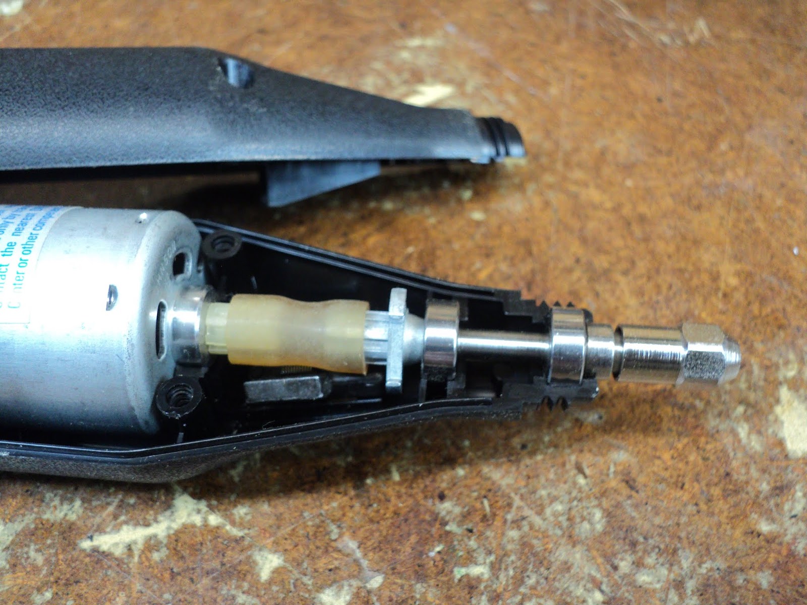
But it's old. Its Ni-Cd battery isn't holding a charge all that well, which comes as no surprise. What did surprise me was a failure in its drive-line -- a plastic flexible coupling sleeve embrittled and broke down, rendering the tool completely inoperative. Here's a view of the failure.


The outboard portion of the sleeve had fallen to pieces, which I've removed. The inboard portion of the sleeve is still there on its spline.

I removed the remainder of the flexible coupling sleeve, and went for a rummage through my stash of plastic tubing. That got me some thin-walled stuff with a 1/4" inside diameter that looked like it might serve. I cut a 7/8" length of the tubing and force-fitted it onto the driving and driven splines, like so.


'Buttoned up the casing and the tool appears to be useable now. I'll keep it in its charging stand continuously charging (the user's manual says it's alright to do that), and see if the tool makes itself useful.

# # #


# # #

Tuesday, January 29, 2019

A Toy Tow Truck's Dome Light From Patio Lantern Circuitry


I have a relic of my boyhood that resides on a shelf -- a toy tow truck with a flashing dome light.


I've made some small improvements to it over the years, most notably to the switch that operates the dome light off the front axle's rotation.

The original switch was an unreliable affair, so I bypassed it with a microswitch. Here's a view of the truck's underside where the microswitch resides.


That microswitch arrangement worked out well, but the dome light itself wanted improvement. The original dome light was a No. 112[1] incandescent bulb. The effect from it was lame. In operation, the bulb would barely get to incandescence before it got switched off again by the front axle's rotation. Some work that I'd done with solar patio lanterns led me to think that patio lantern circuitry might be applied to the problem to good effect.

I stripped down a patio lantern circuit board to its bare essentials, and installed it in the truck. I soldered the LED to the miniature screw base of a burnt-out light bulb, with the cathode connected to chassis ground. That turned out ok, and worked way better than the incandescent bulb ever did. Here's a view of the little circuit board residing inside the cab of the truck.


And here's a brief video of the dome light in action.


I know it's not great, but it's a big improvement over the incandescent.

Here's the schematic of the circuit.


Notes On The Schematic
  • Diode D1 could be omitted altogether. I just left it in place to save myself the trouble of removing it.
  • Pin 2 of the IC is the chip enable (CE) signal. That pin appears to be internally pulled down to the enabled state, so there was no need to ground the pin.
* * *

Note:

[1] The No. 112 bulb is a TL3, miniature screw base, lens-end bulb rated at 1.2 volts, 220 milliamps.

# # #


# # #

Sunday, January 27, 2019

A Toy Model T Ford From The GREAT BOOK OF WOODEN TOYS


Built from a plan in the book, "GREAT BOOK OF WOODEN TOYS" by Norm Marshall and Bill Jones.


A pretty good outcome. I've built a number of toys from the above cited book, and they've all turned out ok.

Mr. Marshall was a brilliant designer; all of the toys in the book are exquisite toy caricatures of the real things. That said, I have a few issues with the book.

First off, the book's front cover carries a sub-title of sorts, "More Than 50 Easy-to-Build Projects". [My emphasis.]

Hmmm. Maybe it's just me, but I'd say that the toys are far from 'easy-to-build'. They call for a well-equipped shop, and many of the operations needed to complete a toy are challenging.

The dimensioned line drawings often lack crucial dimensions/placements. Whoever drew them was not a skilled draftsman.

The photographed prototypes are very fine -- they exhibit superb craftsmanship and technical execution. The text's advice on how to achieve similar results is sketchy at best. I especially take issue with the instructions given about fabricating wheels with hole saws.

Hole saws are rough-and-ready tools for the construction trades. They're for cutting holes through joists for the passage of plumbing and wiring material. They're not designed to create clean discs to be used as toy wheels, as the author would have one believe. I attempted the hole saw method for making wheels for this project, and here's a view of what I got from a couple of Milwaukee[1] hole saws.


Rough, nasty facsimiles of wheels that sanding on a mandrel probably can't salvage -- nothing like the clean, slick wheels seen in the book's photographs of the project. My only use for hole saws anymore is to cut oversize blanks that can be lathe-turned to size on a mandrel. That's how I got the wheels you see in the top photograph.

- - -

Anyway, I sstained the Model T with Minwax No. 235 Cherry Wood Finish. Here's a view of the final product.


Not great -- blotchy and uneven. It will have to do.

* * *

To sum up my take on the book, it is indeed loaded with excellent, charming toy designs. They are not 'easy-to-build'; they're quite challenging.

* * *

Note:

[1] Most of my hole saws are Milwaukees; those are widely available. I have one Diablo hole saw. The Diablo seems to produce a finer cut than do the Milwaukees, so there are variations in cut quality between manufacturers. Still and all, I find the book's emphasis on hole saw wheel making to be misguided.


# # #


# # #
Thursday, January 17, 2019

A 12V Power Supply For CB Radios And The Like


Now and then, old CB radio sets come my way, and I needed a suitable power supply to bench test them with. Here's a view of the rig that I came up with.


The unit at the left is an ancient Canadian Tire Motomaster battery charger, Cat. No. 11-1568-8. A battery charger of that type has no filtering or voltage regulation; it's just a transformer and a full-wave rectifier. At the 2A setting, average dc voltage out is about 11.9V. At the 12A setting, average dc voltage out is about 13.1V. I don't use the 70A setting; I suspect that it's stressful for the transformer.

I modified the charger for my purpose here by nipping off the original clip leads, then adding an output terminal block, output banana jacks and a chassis-ground/earth terminal.


Here's an inside view of the rear of the charger's front panel.


I added fork terminals to the clip leads, so I can still use the charger for its original purpose, like so.


The Regulator

The regulator box in the centre of the first photo above is something I cobbled together from odds and ends that I had on hand, and a new Hammond No. 1411PU aluminum utility case. Here are some views of it.


Output voltage range is about 1.2VDC to 16VDC. The LM317 regulator IC is good for about 1.5A.

Here's the schematic.


1.5A is plenty of current supply capability for a receiver. It appears to be marginal for transmission, though. I may want to look into boosting the regulator's current capability.

- - -

Current Capability Boosted -- WEDNESDAY, FEBRUARY 20, 2019

I was using the regulator to power a vintage xenon-tube timing light, and having trouble with the timing light overloading the regulator. So, I decided it was time to beef up the regulator's current capability.

The way I did it is considered to be bad practice, but I went ahead and did it anyway. I added two LM317s directly in parallel with the first one. That more-or-less works. I've got regulation up to well over 3A output.

The argument against directly paralleling three-terminal regulators is that there's likely to be imbalances -- the regulators won't share the load equally because of tolerance variations. No doubt that's true, but the method appears to work adequately well enough for my purposes. It may have helped that I used three regulators from the same manufacturer, all with the same date code.

Here are views of the modified regulator.


It's not the most elegant wiring job I've ever done, but it works.

And here's the revised schematic.


# # #


# # #