This thing has been languishing in a drawer for decades now.

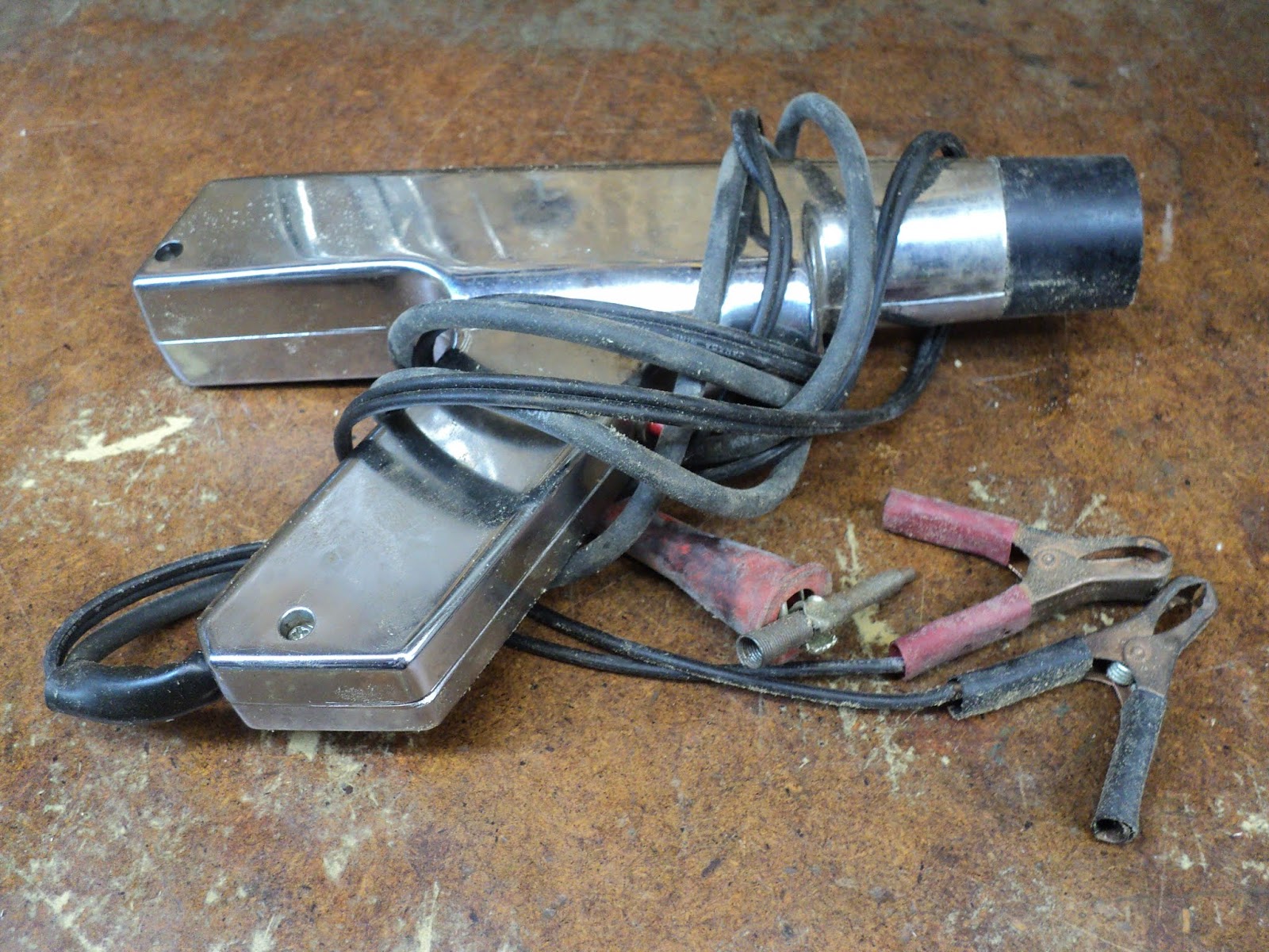
Does anyone still use these? Canadian Tire lists a couple of models, so I guess there's still some use for them -- by those who work on vintage cars and trucks, I imagine.
I opened it up just for a look-see what's inside.

Yikes! I'm not even going to try to reverse engineer that -- too many mystery components.
- - -
I buttoned it back up and tried powering the thing with a 12V, 1.5A bench power supply. That worked, and I was able to briefly test the light with my spark generating apparatus. Then the light quit working, and started overburdening my power supply. I may need to get a lead-acid battery to power it with while I troubleshoot it, and I may need to reverse engineer it after all.
- - -
Progress -- THURSDAY, FEBRUARY 21, 2019
I decided that I don't really want to be the owner of a 12V lead-acid battery. Instead, I set about beefing up the output capability of my bench power supply. That worked out well enough, and let me carry on with troubleshooting the timing light.
- - -
Troubleshooting And Reverse Engineering
It turned out that the timing light was drawing too much current because the inverter wasn't oscillating; it was just loading the power supply. So, I set about reverse engineering the timing light. Following are the two schematics I came up with; one for the primary (inverter) circuit, and one for the secondary (DC power supply) circuit.


Following are some notes on the schematics, and my experience with troubleshooting the thing:
- I can't vouch for the absolute accuracy of my schematics. Reverse engineering is a tricky business, fraught with booby traps.
- Transistor Q1 was fried and leaky. There was no part number on Q1, so I went for a rummage through my stash of transistors. On the basis of a SWAG[1], I chose a TIP122 NPN Darlington for a replacement. With the new transistor installed, the unit was still inoperative.
- The passive components all looked to be more-or-less ok.
- Electrolytic capacitors are notoriously failure-prone[2], so I replaced C3 with a 4.7µF, 63V item, even though the original looked reasonable on a capacitance meter. That fixed it.
- - -
A Video -- FRIDAY, FEBRUARY 22, 2019
I made an attempt at video recording the timing light in action on my spark generating apparatus. The video opens with the apparatus idle at top dead centre. (White marks on cylinder cooling fin and flywheel fin aligned.) Further on, in dim ambient light, you can see the timing light capturing spark occurrence. Spark occurrence is a few degrees before top dead centre. Here's the video.
* * *
Notes:
[1] Scientific Wild-Ass Guess.
[2] I've known electronics 'technicians' who could scarcely read a schematic, or operate an oscilloscope, yet they did a credible job of troubleshooting and repairing electronic equipment failures. If they knew little else, they knew that electrolytic capacitors are failure-prone. That bit of knowledge goes a remarkably long way in the electronics troubleshooting field.
# # #
# # #
No comments:
Post a Comment