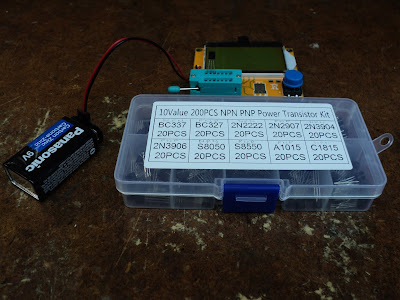
I bought a Kuman multifunction component tester from Amazon recently. Here's what comes in the mail.
There's no documentation with it at all. Here are the features and specs directly from Kuman's website:
Features:
● Multifunction tester: resistor + capacitor + diode + SCR + inductance + Transistor + mos tube.
● Automatically detect NPN and PNP transistors, N-channel and P-channel MOSFET, diode (including dual diodes), transistors, resistors, capacitors, thyristors and other components.
● Automatic power off function, save unnecessary time and battery capacity , Automatic test the pin element and the display on the 12864 LCD Display.
● Accurately report capacitance, inductance and resistance. It's also able to show the layout and type of transistors/MOSFETs, forward voltage of diodes.
Specifications:
● Material: Plastic, metal
● Automatic power off
● Power Consumption Off Mode: Less than 20nA
● Capacitor Measure Range: 25pf -100000uf
● Inductance Measure Range: 0.01mh-20H
● Resistance Measure Range: 0.1ohm resolution, maximum 50M ohm
● Power: 9V battery (If longer power, you can use pack consisting of two 8.4V lithium battery)
● LCD resolution128*64
● LCD Display Color: Green,yellow
● PCB Size: 2.86x2.37x0.047inch ( L*W*T)
● Weight: 45g
Packing List:
● 1 x Transistor Tester
● 1 x Acrylic shell
● 1 x screwdriver
The PCA (printed circuit assembly) is fully assembled and ready to go; it just needs a 9V rectangular battery. Operation is simple enough -- press the blue button and a test cycle commences. You first see this.
With the test socket empty, you then get this.
Note the pin numbering alongside the 14-pin DIP ZIF socket. There are actually only three active locations, but 'pin 1' is repeated (paralleled) four times. The entire seven pin sequence is repeated (paralleled) along the lower course of pin sockets.
What attracted me to the device was the inductance measurement feature. Inductance is surely the most mysterious of all electrical phenomena, and instruments for measuring it are uncommon. I have a selection of ±10% miniature inductors, so I thought I'd put the instrument through its paces with them. Following is the list of my results in the form 'nominal/measured' for fifteen items. All values are millihenrys.
.010/.01
.015/.01
.022/.02
.033/.03
.047/.04
.100/.08
.150/.12
.220/.17
.330/.28
.470/.47
.680/.58
1.00/.94
2.20/1.7
3.30/2.7
4.70/3.6
Hmmm. The measured values are mostly 'ballpark' at best. 'Can't say that I'm impressed.
I've half a mind to return the thing, but maybe I'll hang onto to it, if only as a novelty piece of test equipment.
If and when I fully assemble the unit in its clear acrylic casing, I'll post photographs. And I'll let you know if I find the thing to be actually useful.
- - -
Update -- THURSDAY, APRIL 19, 2018
'Pleasantly surprised by the unit's performance as a bipolar transistor tester.
I'd recently acquired a box of ten transistor types from Amazon, so I thought I'd try out the tester with them.
Something went amiss with my first attempt -- the tester identified a transistor as a diode. Whatever that was all about, the problem went away and never resurfaced. From there on the tester performed flawlessly for identifying polarity and pin-out of all ten types. The tester also gives an 'hFE' gain figure, and a 'Vf' figure. (It's not entirely clear to me what 'Vf' is. Collector-Emitter forward voltage drop, I imagine.) A typical read-out looks like this.
So, I guess the thing is a keeper. I'll peel the paper off the acrylic casing segments, and assemble them.
- - -
Here's the device mounted to the casing's rear panel.
Note that I've routed the battery wiring to the inboard side of the lower left spacer. If the battery wiring is allowed to go to the outboard side of that spacer, the wiring will interfere with the fit of the left side panel.
And here's the completed instrument.
Following are a few points regarding final assembly of the casing.
- Note the notch in the left side panel that accommodates the ZIF socket's lever when the lever is in the closed position.
- Fit of the upper panel was imperfect; the ribbon cable for the display tends to push the rear panel outward, making it difficult to fit the rear panel's upper tab into its slot in the upper panel. I had to file the slot for the rear panels's tab a little in order for everything to go together nicely.
- The screwdriver supplied is a Phillips No. 0. The screw heads' recesses are actually sized to take a No. 2 driver. You'll want a 5.5mm open-end wrench or nutdriver for the hex nuts. (7/32" substitutes ok for 5.5mm.)
# # #
# # #


No comments:
Post a Comment