Thursday, January 22, 2015

Delta Model 36-070 Mitre Saw


My son acquired an old specimen of the subject mitre saw recently for very little money, and it looks like he got lucky -- the saw did a useful job for him on some renovation work at his home. Here's a view of the machine.


Since he has no immediate further need of the saw, we thought it would be a good idea to give the machine a teardown, inspection and some TLC, so there'll be no surprises come the next time the saw is needed.

This post will serve to document my work on the saw. The material that shows up here may not always be in the most coherent, linear order; I'm not claiming to create a proper service manual.

Motor Brushes

Brush access is good. Remove three M4x16mm truss head threading screws, and you can pull off the motor's end-cover.[1] That gets you to here.


When removing brushes that will be re-installed, it's a good idea to unambiguously mark the holders and brushes, so you can get them back in place exactly as they were. Old brushes will have mated themselves to their original installation, and will last longest if returned to that installation. Just make some dot marks with an engraver to tell you what goes back where.


The brushes from this motor look fine -- evenly worn, and with plenty of length left to go.


- - -

Blade Removal

Remove the blade guard to gain access to the blade's fastening screw.

There's a single M6 hex socket head cap screw that secures the blade guard adjustment link.


Remove that screw with a 5mm hex key, and it's pretty obvious from there on how the blade guard comes off.

A 13mm A/F hex washerhead screw secures the blade.


The screw has a left hand thread. To remove it --
  • Lock the saw's arm in its storage position. (There's a locking plunger at the upper right side of the pivot column.)
  • Jam the blade with a scrap of hardwood.[2]
  • Turn the screw clockwise.
Like so.


And if it weren't for the seven chipped teeth, this saw would have a very nice 40-tooth Hitachi blade on it.

- - -

Motor/Gearbox Removal -- FRIDAY, JANUARY 23, 2015

Three M5x75mm screws secure the motor/gearbox assembly to the saw frame.


I'll clean everything up with compressed air, then decide whether I should open up the gearbox to re-grease it.

- - -

I decided to leave the gearbox unopened. Given the condition of the brushes, there can't be a lot of run time on this unit, so there's really no compelling reason for me to relubricate the gearbox at this time.

- - -

Blade Guard Adjustment -- SATURDAY, JANUARY 24, 2015

When we got the machine, its blade guard was inoperative -- the guard was jammed in its fully raised position. It turned out that the guard had been deliberately mis-assembled to disable it, and keep it raised at all times. Now that I have the guard working, I think I see why the original owner disabled it.

The guard's default geometry is such that guard operation adds a little to the force needed to start lowering the saw to make a cut. There's an adjustment that can be made to correct that. Here's a view of the guard's at-rest state as the factory no doubt sets it up.


Note that the guard is fully lowered/closed; the rear edge of the guard is stopped against a small, round bumper. Opening the guard from that position takes a perceptible bit of force, and a user might find that characteristic of the guard annoying.

The at-rest position of the guard can be adjusted so that the guard never fully closes, and that does away with the effort needed to start the guard opening. The attendant loss of guard protection is minimal.

To make the adjustment, loosen off the screw in the middle of the short link at the left with a 5mm hex key. Alter the guard's at-rest position so the guard is partly open when at rest, and retighten the screw. The guard's new at-rest position will look like this.


Note that the rear edge of the guard no longer contacts the bumper -- it comes to rest about an inch away from the bumper. By introducing that partially-open condition to the guard's at-rest state, the effort needed to start further opening the guard is made negligible.

- - -

Notes:

[1] All three screw well bottoms were broken out of the cover on this unit. The same thing probably happens to all of them. I glued the well bottoms back in place with CA adhesive. Here's a view of the inside of the cover after repair.


Update -- SATURDAY, JANUARY 24, 2015

That repair failed. I redid the repair by using long enough screws to secure the cover by its outer end surface, like so.


The hardware complement there is:
  • 1x No. 8 x 1 1/4" flat head wood screw.
  • 2x No. 8 x 2" flat head wood screw.
  • 3x 3/16" fender washer.
  • 1x No. 8 cup washer.
End of that problem.

[2] Alternatively, you can hold the blade from turning by means of a 5mm hex key inserted into the motor's shaft-end at the right side.

# # #


# # #

Sunday, January 18, 2015

Christmas Tree Stand Clamp Screw Thread Marginality


How's that for a blog post title -- "Christmas Tree Stand Clamp Screw Thread Marginality"? It's a bit wordy, but it does convey the problem.

This Christmas tree stand has a clamp screw thread that's all but fully stripped.


The M8 screw won't apply pressure when tightened -- it just skips its female thread to no effect. (It never ceases to amaze me how manufacturers can't seem to master the simplest aspects of low-tech goods, yet they can produce high-tech items of stunning precision and perfection. It's a mystery.)

The female thread that's at issue here was poorly formed in thin material, hence the marginality.


What I'll do is fabricate a rectangular nut-plate from 3/32" thick steel flat. That will give me a nut that's inherently restrained from turning as the screw is turned. The nut-plate will tuck away neatly in its recess, and won't even be visible.

- - -

And here's the nut-plate fabricated and in place.


End of problem.

* * *

Not Quite -- SATURDAY, DECEMBER 31, 2016

The screw on the opposite side developed the same problem this year -- I gave it the same treatment as last time to repair it.

The root of the problem is not entirely with the female threads; the M8 screws are considerably undersize, contributing to marginal thread engagement. If there's a recurrence of the trouble, I'll replace all four screws as well as provide new female threads.

The stand's design is good, but the manufacturer's execution was poor. Properly made, one of these stands could last for generations.

One  wonders how many of these stands failed in this manner, and ended up in landfill. The waste is enormous, but then it's waste that makes the economy go round.


# # #


# # #

Saturday, January 10, 2015

A Handwheel For A Wood Lathe Without One


A recent wood lathe restoration project has left me with a nicely working wood lathe that lacks a handwheel for the headstock spindle.


I find myself using the cone pulley for a handwheel -- not the safest practice.

So, I'll make a wooden handwheel for the machine, using a 2" pulley as a hub.

Here's what I have to start out with.


That wood is softwood, which is not the best material for this. I'd be better off using a close-grained hardwood like maple, but I don't have any that's suitable. I'll go with the softwood, and see what sort of result I get. I can always make a new, better wheel if and when I obtain some better material.

- - -

And here's the pulley at the drill press getting four 5/64" pilot holes drilled for fastener locations.


Starting a drill on a sloping surface like that is a bit of an iffy proposition. I was able to get a reasonably precise, if not entirely perfect result.

Here I've bored the pilot holes out to No. 25 drill diameter, for tapping 10-24.


Before tapping the fastener holes, I faced off the rim of the pulley, to ensure that the handwheel will run true.


And here we are with the pulley's fastener holes having just been tapped 10-24.


Here's the wooden handwheel blank assembled to the pulley, and mounted for turning.


The screws are 10-24 x 1 1/2" round head, with No. 10 SAE flat washers under their heads. I installed the screws with blue threadlocker, so they won't loosen off on me.

And here's the finished item, turned, sanded and ready for installation.


Finally, here's the handwheel mounted on the outboard end of the headstock's spindle.


Much better.

The handwheel isn't perfectly balanced. At the lathe's highest speed, there's a slight but perceptible vibration. I've yet to have had need of that speed, so I'll just work with the handwheel as it is for awhile, and see if it's satisfactory otherwise. I can look into how I might correct the imbalance later.

- - -

Further To Imbalance -- SUNDAY, JANUARY 11, 2015

I put a dial indicator on the rim of the wheel, and discovered about 0.030" of radial runout. That probably came about while sanding the rim of the wheel, and no doubt accounts for much, if not all, of the wheel's imbalance.

Sanding on the wood lathe will tend to remove material non-uniformly, according to density/hardness variations around the circumference of the object being sanded. There's a 'path-of-least-resistance' effect that results in out-of-roundness. For a static, artisanal turning, the out-of-roundness is unlikely to be perceptible, or to matter at all to the usefulness/quality of the finished item. For a machine part, the out-of-roundness may matter, as it appears to here.

What I'll do is is I'll carefully re-turn the rim of the wheel with a sharp gouge, and forego sanding it. That should result in a truer wheel. We'll see.

- - -

I re-turned the rim of the wheel and left it unsanded. The measured radial run-out is now about 0.012", and the wheel's balance seems to be slightly improved.

Anyway, the arrangement is perfectly acceptable. I'm not going to fiddle with it any further. I'll just give the handwheel feature a good trial as I continue to use the lathe, and see how I like it overall.

- - -

A Small Improvement -- MONDAY, JANUARY 12, 2015

I deleted the round head screws and flat washers that I had used to fasten the wheel to the pulley, and replaced them with flat head screws.


Now there's nothing protruding from the face of the wheel when I use the wheel as a 'brake'.

- - -

I Forgot Something -- MONDAY, JANUARY 19, 2015

A hole for the knockout bar to go through.


There. Now the wheel has an 11mm diameter hole through it for the 10mm diameter knockout bar to slide through.

# # #


# # #

Wednesday, January 7, 2015

Choosing And Siting A Wood Lathe's On/Off Switch


I've restored a decrepit old wood lathe recently, and chose to site the on/off switch right by the headstock, facing up, like so.


In using the lathe, I found that switch location and orientation to be ideal; the switch was right handy to my left hand at all times -- a good safety feature.

But there was a downside; the rocker-style switch tended to get loaded up with dust and shavings something awful.


Dust and shavings would sift down into the switch's innards, and render the switch inoperative. A blast of compressed air, and some ferocious switch toggling, would clear up the problem for awhile, but it was an unacceptable nuisance. A more-or-less dust-proof switch was in order.

A style of switch that's relatively dust-proof is a shank-mounted, bat-handled toggle switch, like this one.


You just have to be certain of choosing one that's capable of operating the load involved. The pictured switch is rated for 16 amps, 1 hp, so it's quite adequate for the 1/2 hp motor on the lathe.

A rectangle of aluminum sheet provided for a reworked switch mount, that accepted the shank-mounted switch in place of the original rectangular switch.


And here's the switch all wired up and where it belongs.


And that should be an end to the fouled switch nonsense.

# # #


# # #

Monday, January 5, 2015

A Wood Turning Screw Centre


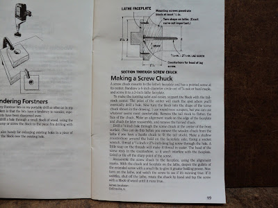
I had need of a screw centre for turning some lids for glass vessels, and discovered that screw centres are about as common as hens' teeth. You're pretty much left with little choice but to fabricate a screw centre when one is needed.

I leafed through a booklet I have in my library, "American Woodworker's Best Jigs and Techniques for Precision Woodworking", by Rodale Press, Inc. and found this plan.


I made up a centre very similar to the one in the booklet. It turned out reasonably well. Here it is mounted on the lathe's spindle nose.


And here it is with a workpiece mounted on it and almost done.


The centre's precision is not perfect, the screw emerges at a very slight angle to the axis, but for my purpose here it's acceptable.

So, there's one less thing to have to go shopping for when it's needed.

# # #


# # #

Saturday, January 3, 2015

Light-Duty Screw Anchoring In Drywall


This method costs virtually nothing, and produces a sound screw anchor for light loads.

- - -

First, run in a short No. 6 drywall screw at the point(s) where you want your anchor(s).

Remove the drywall screw, blow away any dust and pump the hole full of wood glue from a squeeze applicator bottle.

Poke in a straight pin and wiggle it about to distribute the glue within the hole. Wipe away any excess glue with a moist paper towel. Leave the glue to cure overnight.

Install your item using a drywall screw, or any No. 6 screw. For a light, static load like a small notice board, the resulting screw anchor is quite adequate.


# # #


# # #