Saturday, October 19, 2013

A Broken Wing Screw


I went to take a photograph of something on my workbench with the aid of my mini-tripod, and something didn't feel quite right as I tightened the little wing screw that secures the head of the tripod. It turns out there was a good reason for that.


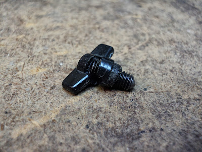
The plastic wing affair broke. Here's a view of the screw removed and on its own.


Piece of junk.

I'll have to get the remnants of the wing off the screw however I can, and see if I have a wing nut that will fit that I can glue on for a replacement wing.

- - -

Here's a method for clamping a screw thread in a vise without marring the thread.


Cut through one side of a hex nut, and use that as a primitive 'collet' to grip the thread in a vise, like so.


Now I can get pliers onto that wing remnant and crank it off the screw.

- - -

That worked fine, but my 'collet' didn't want to unscrew easily after having been clamped onto the screw in the vise. I hammered a chisel tip into its saw cut gently to persuade it to open up a bit, and it unscrewed. The chisel's tip never reached the screw's thread, so no harm was done.

- - -

I happen to have exactly one M5 wing nut in my stash of M5 stuff. Here, I've attached it to the screw using CA adhesive as a threadlocker.


Back in business.

# # #


# # #

Recapping Tubes Of Sealants


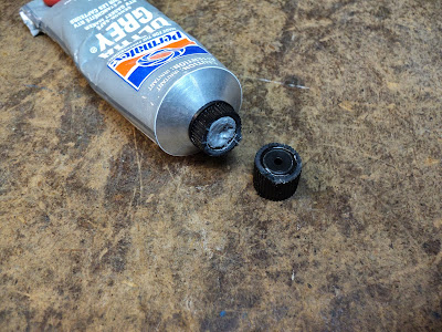
Don't let this happen to you.


That's what happens when you over tighten a tube's cap. It's not helpful.

The temptation to over tighten is great; after all, you don't want the material to harden in the tube. Resist the temptation, though. Just snug down the cap and leave it at that. Further tightening past the point of closure only leads to the pictured result.

# # #


# # #

Tuesday, October 8, 2013

Ryobi 10" Table Saw (BTS12S) -- Tilt ('Bevel') Mechanism


I was given a broken down old BTS12S that I've been restoring to working order. I've got the saw running, but there's a curious problem with the 'bevel'/tilt[1] mechanism. Permit me to back up a little, and describe the whole elevation/tilt operation of the machine.

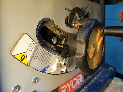
On the BTS12S, a single handwheel operates both blade elevation and blade tilt. The default position of the handwheel is for it to engage the elevation screw. Pushing the handwheel in against a spring disengages it from the elevation screw, and engages a rack-and-pinion gear set that operates the tilt function. The problem I have with the machine is that the rack-and-pinion gear teeth barely engage one another deeply enough to work -- the teeth mostly just skip to no effect. I can see no adjustment to improve the gear teeth engagement. Here's a view of what I've just been on about.


Everything about the mechanism appears to be factory-issue, which says that the tilt function on this saw has never worked, right from day one. That likely wouldn't have mattered to the guy who gave me the saw, because he was only using the saw to cut up shipping pallets into firewood. Regardless, whether I keep this saw or give it to someone, I'd like for the tilt function to work as it ought to.

From what I can see so far, it looks to me like the elevation screw emerges at the front of the saw too low down for the rack-and-pinion gear set to ever engage properly. I need to see if there's a way I can alter that, without fouling up the elevation function.

- - -

Here's a view of the front of the saw upside down with the handwheel and elevation screw removed.


Note the position of the large washer just inside the tilt slot where the elevation screw emerges -- it's not centred, it's almost as far away as possible from the rack. It's beginning to look to me like Ryobi got a dimension wrong, and may have made many of these saws with this same defect.

I've removed the washers and spring that are immediately behind the tilt slot, to get a direct view of the hole in the tilt carriage that the elevation screw emerges from. Here's a shot of that.


The photograph shows it poorly because of a shadow, but that hole is way too far from the rack for the elevation handwheel's pinion to ever engage the rack fully.

I'll try elongating that hole in the direction of the rack, so that the elevation screw can be manually forced toward the rack when the tilt function is engaged.

- - -

Well, the job I did of elongating the hole with a hand grinder is not pretty, but it did yield the outcome I was after; it's now possible to force the rack-and-pinion to engage fully. The tilt function is operable throughout its entire range.

Conclusion

I'm normally disinclined to condemn a piece of engineering, I know that there are many compromises that must be made, but for this tilt mechanism I'll go right ahead and condemn. The tilt mechanism is, in a word, shabby. It never should have left the factory. What respect I ever may have had for Ryobi has taken a nosedive with this little exercise. I consider such marginality in a mass-produced, low tech piece of gear to be inexcusable.

If you're shopping for a legitimate woodworking machine for cabinet making and the like, steer clear. If you're looking for a firewood cutter, the Ryobi will serve. That's the class it's in, after all.

- - -

Note:

[1] Ryobi insists on referring to 'tilt' as 'bevel'. Tilt and bevel are not the same thing; bevel is an effect, tilt is a cause. Setting the blade's angle to something other than ninety degrees via the tilt mechanism bevels nothing -- it merely tilts the blade. Cutting wood with the blade tilted results in a bevel.

It appears that Ryobi's grasp of English is as marginal as its tilt mechanism.

# # #


# # #

Friday, October 4, 2013

A Light Switch Failure -- Or -- Some Things Just Aren't Repairable


I had a light bulb socket with a built-in push-button switch become troublesome, so I took the thing apart to see what the problem was. Here's a view of the switch's innards in the 'off' position.


The spring-loaded contact-closure bar is flipped over to the right, well away from the two curved springy contacts; the switch is 'open'.

And here's a view of the 'on' position.


The contact-closure bar is flipped over to the left, where it's firmly shorting the two springy contacts together; the switch is 'closed'.

The mechanism is working as it should, but there's a problem that the above two photos don't reveal. The lower one of the two springy contacts is quite worn out, like so.


(My camera is barely capable of getting a grip on an object so tiny. The above is the best I could do.)

The contact has been impacted by the closure bar so often that a notch has been worn clear through it. The switch is finished.

So, it's off to the landfill for this switch. Some things just aren't repairable.

# # #


# # #

Thursday, October 3, 2013

A Wooden Frame For A Small Parts Carousel


* * *

[Note: Rouge River Workshop's author is and has been having a spot of mid-life crisis. Between a prolonged illness, and lay-off from employment back in May of this year, life has left a bit to be desired lately.

Anyway, I'm on the mend now, and have a great deal of catching up to do on many fronts. My blogging here is going to suffer for awhile because of that. This post is much abbreviated from what I would normally present. 'Abbreviation' is likely to be a feature of much of what little I'm able to post for the near future.]

* * *

I brought this item over from the garage.


If you read the linked post, you'll have gotten the introduction to this brief post. What it boils down to is that I have to fabricate a wooden frame for the carousel, to substitute for the original steel frame that's gone missing. Here goes.

- - -

The Frame

Here's a view of what I've come up with for a frame.


The carousel fits easily between the two side frame members, which raises the problem of bearings that can 'reach in' to support the carousel. Here are the bits and pieces I came up with to deal with that issue.


The threaded rod pieces are 1/2"-13, with a 5/8" deep, 5/16" diameter bore at one end -- those are my adjustable bearings that do the 'reaching in'. The rest of the stuff is to assure secure bearing retention in the frame -- the bearings mustn't be free to 'walk' out.

Here's a view of a completed bearing assembly from the outside.


Inboard, the bearing relates to the carousel like so.


So far, so good. Now I have to find a place to install the thing.

My workshop's wall space, and overhead space, are pretty much taken up with stuff already. When I find a place for the carousel, I'll be back with a photo of it. Meanwhile, at least I've got a satisfactory replacement frame to take the place of the missing one. This carousel is something I rememeber from early boyhood, so I couldn't just let it languish in the attic. It pleases me greatly to have the use of it.

- - -

Installed -- FRIDAY, OCTOBER 4, 2013

As promised, here's a view of the installed carousel.


That's the headstock end of my metal lathe's bench that the carousel is now attached to. All things considered, that's not a bad place for it.

# # #


# # #