Sunday, November 27, 2011

Running a Scroll Chuck in Reverse

To run a scroll chuck in reverse, there has to be a means of locking the chuck onto the lathe's spindle, else the chuck is likely to unscrew from the spindle at start-up and wreak havoc.

I had need of reverse operation yesterday for sharpening the stylus of an electric engraver, and came up with a quick-and-dirty way to secure my lathe's chuck. I'm not sure the lathe police would approve, but it did work with a 1,000 rpm spindle speed.

The hub of my lathe's spindle is the same diameter as the hub of the chuck's back plate, as you can see in the following photo.

('Sorry about the dreadful lighting. Some things can be incredibly difficult to light properly.) I installed two identical hose clamps with their heads opposite one another, and tightened them very securely, like so. It got the job done. (If you'd care to see that, it's 'Addendum II' to this post -- scroll way down.)

I took the hose clamps off this morning, and there was no evidence of the chuck having loosened at all.

That said, I really should look into a sounder method of securing the chuck for reverse operation.

# # #


# # #

Saturday, November 26, 2011

Elephant Cleaning

The things I get called upon to do around here.

Some clever retail employee wrote directly on the poor thing.

Lacquer thinner got most of it. Some sanding is in order.

And there we are; 220-grit garnet paper got it looking spiffy.

Now that pachyderm can rejoin its herd without fear of being teased about its 'disfigurement'.

# # #


# # #

Sunday, November 20, 2011

An Unorthodox Hose Faucet Installation

My workshop has a sink where I can do the sort of washing up chores that are best not done in more refined environs. What I lack, though, is a faucet that I can connect a hose to for things like my faucet test fixture. I've thought of a way to add such a faucet to the workshop's sink without having to make a full-blown plumbing project of it, with all the attendant hassle of shutting off the house's water and all. We'll see how it goes.

- - -

The Unorthodox Part

I've made up the bits needed to make possible what I have in mind. Here's a view of them.

The 3"long 1/2" NPT pipe nipple was drilled through at two places and tapped 1/4"-20. The undersize 1/4" flat washers are No. 8 washers that I bored out. In back are a steel flat mounting plate and a hardwood spacer.

I'll assemble the pipe nipple to the steel flat with Permatex Ultra Grey RTV gasket maker, and then I'll have the basis for my faucet installation.

- - -

And here it is assembled.

Now I can attach the nipple to the edge of a stud that's right by the sink, and add a faucet.

- - -

And here it is in place at the sink.

I haven't connected it to its water supply yet. That connection will be a 3/8" compression fitting connection. The 1/2" F.I.P. (Female Iron Pipe) hose connection at the right side of the photo raises an interesting point about pipe threads.

- - -

Pictured below are two examples of 1/2" M.I.P. (Male Iron Pipe) threads, along with a 1/2" F.I.P. hose-end fitting.

Pipe threads for assembling pressure-tight joints with Teflon tape, or some other thread sealant, are tapered, so the male and female threads will wedge together as a joint is tightened. (The taper is 1 in 16 as measured on the external diameter.) The fitting at the right in the above photo has a tapered thread.

At the centre is the supply fitting of a Moen faucet. The thread is the same size and pitch (1/2" pipe; 14 tpi), but the thread is straight, not tapered. That's the style of thread that the gasketed hose-end fitting at the left is meant to go onto, but the hose-end fitting also works fine with a tapered thread -- the fitting's gasket engages the end of a tapered-thread fitting well before the increasing diameter of the thread can interfere with the hose-end fitting's fit. That simplified things a bit here in that I was able to use a readily available tapered thread fitting for this; I didn't have to search for a straight thread fitting.

- - -

Problem

I hooked up the hose faucet just for a pressure test, and there's a leak.

I can't say that I'm surprised by that.

Assembling tapered pipe threads is problematical when the nature of the assembly calls for a specific angular position to be achieved, as was the case here. The copper sub-assembly had to end up with the hose-end fitting pointing down. Once I got it more-or-less snug that way, it didn't feel to me like there was one more full turn to be had from the threaded fitting, so I left it at that. As it's turned out, one more full turn would have been in order.

I'll take that fitting apart and reassemble it with silicone RTV gasket maker for a thread sealant. Once that stuff cures, it'll be end-of-problem.

- - -

Another Problem

Underneath, where the faucet supply valve resides, I had had in mind to install a tee compression fitting to supply the additional faucet, like so.

That didn't work out. I could not get the compression joints at the short length of plated copper tubing to seal properly. (See this post for some lessons learned about compression fittings.)

Time for a rethink. Here's what I came up with.

From left to right, we have the following items:

a) A 12" faucet supply hose with a 3/8" compression fitting at the end you can't see, and a 1/2" F.I.P. fitting that you can see.

b) A 1/2" to 1/8" pipe thread adapter that's had its 1/8" pipe thread bored out to 3/8".

c) A 3/8" compression fitting nut.

d) A 3/8" compression sleeve.

e) A 7/8" length of hard, thin-walled brass tubing.

f) The 3/8" compression tee seen in the previous photo.

And here is all that assembled, soldered and cleaned up.

And here it is installed and pressurized.

The outlet for the hose faucet is capped. Tomorrow, the RTV gasket maker in the pipe threads will have fully cured. I can do the final hook-up and I'll have my indoor hose faucet.

- - -

And here it is all together and working.

Now I can attach a hose indoors for connecting any sort of pressure-test fixture, and the faucet is high enough for filling a big bucket if need of that should arise.

Whatever Rouge River Workshop wants, Rouge River Workshop can fabricate.

# # #


# # #

Saturday, November 19, 2011

Boost/Jump-Starting a Vehicle

Jump-starting a vehicle is a pretty straightforward proposition, but boo-boos must not be made -- the potential exists for boo-boos to be punished severely by attendant phenomena.

Jump-starting carries with it two risks that one must be mindful of. They're easily eliminated.

Short-Circuit Risk

If inadvertently short-circuited, a charged lead-acid battery will deliver a massive amount of electrical energy to the short-circuit. The consequences of that can be nasty. Make connections one polarity at a time -- i.e. positive-to-positive; negative-to-negative. Never connect a cable set to a booster battery with both the other cable ends left unconnected.

Explosion Risk

The risk is small, but it's not zero. It's greater with unsealed batteries (the type with screw-off caps on the cells for adding water).

A characteristic of lead-acid batteries is that while charging, the cells can emit hydrogen and oxygen that results from electrolysis of water. Needless to say, one doesn't want to introduce sparks to such a gas mixture. Adhering to the correct cable connection sequence and method pretty much eliminates the risk.

Cable Connection Sequence

1) Positive connection at dead battery.

2) Positive connection at booster battery.

3) Negative connection at booster battery.

4) Negative connection at dead vehicle.

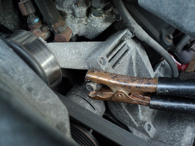
It's that fourth connection that's fraught with peril. Some sparking is very likely to occur as the connection is made. That's actually normal, and not a cause for concern. Ideally, though, the connection should be made not at the dead battery, but at a good, clean ground point on the engine/chassis/body. On some vehicles, a good ground connection point is easy to come by. Here's an example.

That idler pulley bracket on my 3.0 litre Ford Ranger is a good place.

Some vehicles can be remarkably difficult to find a good ground connection point in aside from the battery terminal itself. A very good way to deal with that is to install a purpose-made, dedicated jump-starting ground terminal. I'll put one in the Ranger to demonstrate.

The Ranger's front bulkhead has a nicely positioned 1/2" hole in it already, just below where the hood rod is attached. I took the Dremel grinder to its perimeter and got down to bright, naked steel all around it, like this.

Should you have to create a hole for the purpose, use a chassis punch. A 1/2" twist drill applied to sheet metal will give rough, nasty results.

A 1/2" x 1 1/2" bolt, two nuts and three washers will make a fine terminal.

Use only new, oxide-free parts. Lubricate everything with WD-40, install and tighten for all you're worth. Here's how it looks when done.

And now, when your battery dies in the beer store's parking lot in the rain in the dark, you won't have to search for a good, clean, safe ground terminal to make your fourth connection to. One will be right there ready.

Give the terminal a shot of WD-40 whenever you have the hood open, and you'll always have a clean connection point for a boost.

- - -

One last point about connecting cables -- don't be gentle about it. Connection points are likely to be oxide-coated. Gently clamping onto them will be ineffective; an oxidized battery terminal may as well be wrapped with electrical tape -- oxides are that good an insulator. As you apply each clamp, rock it so it can bite through the oxide.

# # #


# # #

Tuesday, November 15, 2011

Battery Replacement -- 1999 Ford Ranger

The original battery in my '99 Ranger finally died on me. That's extraordinary battery life -- I've never seen a battery last twelve years.

Anyway, replacing a battery is a pretty straightforward job, but there is a crucial safety consideration that one is wise to bear in mind.

- - -

Safe Battery Handling

A charged battery, if inadvertently short-circuited by a wrench falling across its terminals, say, will deliver a massive amount of electrical energy to the short-circuit. Such an occurrence can have consequences ranging from merely inconvenient to downright tragic; it must not be allowed to happen.

A battery out of a vehicle presents only the span across its two terminals as a possible short-circuit path. Taping over either of its terminals will preclude the possibility of a short-circuit. (New batteries come with little plastic caps on the terminals.) A battery installed in a vehicle is another matter. When connected in a vehicle, every exposed bit of metal -- body, chassis, engine, everything -- is electrically equivalent to the battery's negative terminal. There are lots and lots of possible short-circuit paths.

That's why, when removing a battery, one always disconnects the negative terminal first. With that terminal disconnected, you're back to having only one possible short-circuit path. Conversely, when installing a battery, one always connects the negative terminal last.[1]

- - -

Replacing the Battery

Here's a view of the battery at the left front corner of the engine compartment.


And here's a view of the single clamp-block that secures a ledge at the inboard-bottom of the battery.

The fasteners are all 8mm A/F hex head. Use only a six-point socket; those fasteners have had a long time to seize, and you'll need all the hex engagement you can get to get them out. Expect snags on an installation this old.

And sure enough, the round, swaged-in-place M6 nut at the negative terminal broke loose.

I managed to get it apart by clamping Vise-Grips on the nut to hold it from turning. Then, I had to bend up two little retaining 'ears' trapping the washerhead screw, so I could get the screw out for a proper wire-brushing.

Holding the terminal with Vise-Grips made it possible to straighten the ears (it's a poorly lit photograph).

The fastening at the positive terminal was uncorroded and loosened easily.[2] With both cables off their terminals, the battery blanket[3] can be slipped off. Here's a view of that.


The M6 screw holding the clamp-block in place was a bit of a struggle. The screw is much longer than it needs to be, which leaves plenty of exposed screw-end to rust. With wire-brushing and WD-40 and much 'toing-and-froing', I got it out. (By 'toing-and-froing' I mean unscrewing until excessive resistance is met, screwing it back in a ways, wire-brushing some more and reapplying WD-40, then unscrewing again until excessive resistance is met. Repeat as needed until the screw comes out. It's tedious, but if you just go straight at it with a big wrench, you're much more likely to break the screw.)

That's all the difficult stuff dealt with. Clean the muck and grime out of the battery pan and off the blanket, wire brush the screws and terminals and the new battery can go in. Here it is with everything buttoned up and ready to go.

That purpose-made wire brush works nicely for scouring battery terminals and connectors. I reassembled all the threaded fasteners using anti-seize compound. Down in front is the round nut that broke loose. I replaced that with an M6 hex nut, lock washer and flat washer.

So there we are. It was a breeze, just like everything in the Haynes manuals always is.

- - -

Notes

[1] What I've been on about here assumes a negative ground vehicle; i.e. battery negative connected to body/chassis/engine. As far as I know, modern vehicles are all negative ground. In early days in the auto industry, Ford and the Brits employed positive ground -- battery positive was connected to body/chassis/engine. I seem to recall that my first car, a 1961 Austin-Healey Sprite, was positive ground. For a positive ground vehicle, all negative/positive terms in the preceding two paragraphs would have to be transposed.

[2] I wish I understood the chemistry/physics/whatever of this. The positive terminal was clean as a whistle; the negative terminal was quite corroded. What's with that?

[3] This is so neat. The battery has a 47 watt electric blankie to keep it cozy on chilly nights in the north. Ford really pulled out all the stops to make this vehicle startable in extreme cold. It came with both a block heater and a battery blanket.

# # #


# # #

Saturday, November 12, 2011

Turning a Centreless Disc From Thin Material

I'm restoring an elderly Moen lavatory faucet. There's a circular concealment cover for the knob's attachment screw that has gone to ruin; a replacement disc of some sort is in order. Here's a view of the ruined one.


I have some thin black plastic that I think was originally an electrical insulation sheet in the chassis of an old slide projector. Here's a way to make a small, centreless disc from such stuff.

That square of wood is attached to my wood lathe's face plate. A slightly oversize square of the plastic material is adhered to the wood square with carpet tape. I squeezed the thing all over in the wood vise, so that plastic is well and truly stuck there.

With a bit of trial-and-error pencil marking with the work spinning, I managed to mark the diameter I was after (32.5 mm). A very careful approach with the pointy end of a 1/2" skew chisel results in this.

A centreless disc.

A small utility knife blade slid underneath the plastic is helpful for coaxing the material off the wood. Varsol is helpful for getting the tape off the plastic. (Carpet tape's adhesion can be quite amazing.)

And here's my new screw concealment cover.


It fits perfectly, which is a good thing. Had it turned out to be too big, I'd have had to start again and make another one. Once off the face plate, there is no practicable way to alter the size of the disc just a little.

# # #

FEEDBACK

# # #

Moen Cartridge Removal With a Slide Hammer

[NOTE -- SUNDAY, NOVEMBER 6, 2011: I've added an important safety feature to the end of this post.]

I have an elderly Moen wash basin faucet that I mean to restore to pristine condition. Moen faucets are a 'cartridge' design -- there's a single element that does all the valving. It ought to be a fairly easy thing to deal with -- just pull the cartridge straight out once you've removed its retainer -- but the cartridge didn't want to budge. A slide hammer came to mind as just the thing I needed.

I have a slide hammer, but it's a great brute of a thing with a five pound slide on it. It's pictured below along with the faucet.

The phrase 'disproportionate force' comes to mind. I could have rigged a means of attaching this hammer to the faucet's stem and used it for the job, but it struck me as a clumsy way to go about it.

So I gave some thought to the matter of what a slide hammer fundamentally consists of, and it turns out that there's a very simple way to construct a light slide hammer.

A 3/4" iron pipe 'tee' is a sliding fit over 1/2" iron pipe -- there's your 'hammer' slide. Put a cap on one end of a length of pipe for a strike, and you have the makings of a slide hammer. Here's the completed hammer having just done the job.

That's an eighteen-inch length of pipe from the Home Depot. I would have gone with only a twelve-inch length for this, but eighteen inches was the closest they had.

I added a plug to the 'tee' to give the 'tee' a little more mass. A cap drilled through to accept a 10-24 screw provided the means of attaching the hammer to the faucet's stem.

It worked beautifully. It couldn't have worked any better if it said "Snap-on" or "Crescent" on it. The corporations don't own the fundamentals of physics.

- - -

Safety Feature -- SUNDAY, NOVEMBER 6, 2011

If you make one of these, I strongly advise you to add the safety feature pictured below.


It's a 2" I.D. x 1 1/2" I.D. exhaust pipe coupler, and a 1 5/8" clamp. Position the clamp so the bracket portion of the clamp straddles the bulge at the tee's opening, and the U-bolt is centred on the bulge. Tighten it very securely, taking care to maintain alignment of the tee and coupler.

This will prevent you from getting your little finger pinched, like I did earlier today. A bonus is that it adds mass to the slide.

# # #

FEEDBACK

# # #

Saturday, November 5, 2011

A Garden Hose Purge Coupling

If you have a reeled-up hose like this, you need to get the water out of it before it freezes come winter.

The way I used to do that was to unreel the hose (all 100' of it), lay it down the length of our down-sloping backyard and let it drain. Then I'd reel it back up (all 100' of it).

This year, while I was getting ready to repeat that chore, the thought occurred to me, "What do I own an air compressor for, anyway?" I set about making an air/water coupler so I could blow the water out of the hose without unreeling it. Here's what I started with.

That hose barb is for 1/2" hose; the male air fitting is an ARO type with a 1/4" NPT pipe thread on its end. The pipe thread almost fits the bore of the barb.

After a few turns into the hose barb with a 1/4" NPT tap, the air fitting with paste solder flux smeared on it can be screwed in a ways. Apply heat and solder and you end up with this.

And now, the hose can stay right where it is on its reel, and you can connect your air compressor to it like this.

Be mindful of where the free end of the hose is when you make the connection, and you may want to throttle back your compressor's outlet pressure to something within reason (30 - 40 psi, say). My compressor's outlet pressure was way high at 110 psi. Nothing untoward happened, but for safety's sake, less pressure might not be a bad idea.

Needless to say, though, at 110 psi the water in that hose took off right quick for the backyard. All of my ideas should work out so well.

# # #


# # #

A Garden Hose Gender Changer -- Male-to-Female

An alternate title for this piece could be 'brain spasm'.

For some reason that I cannot fathom, I got it into my head that I needed a male-to-female garden hose gender changer for something I had in mind. When I got it done and went to carry on with the thing I thought I needed it for, it turned out that no such need existed.

Anyway, I have one now, so if non-hallucinatory need of it ever does arise it'll be right there ready in my hose fittings bin. Here's how it looks.

Those coupling nuts were salvaged from fittings cut off of discarded hoses. Brass or bronze are best for solderability; plated steel ones can be used as well, but soldering them is less easy.

When salvaging a fitting's nut, cutting away the swaged hose-end ferrule and persuading the hose barb to vacate are a bit of a chore, but quite doable. A Dremel cut-off wheel is helpful for getting the ferrule cut through most of the way until you can rip it off. Cut away the hose remnant, and then squish the barb in the vise. Saw off as much of the barb as you can, then punch out what's left with a hammer and a big pin punch.

A 5/16" bolt, two washers and two nuts make an adequate soldering fixture. Here's a view of how I had it set up.

It takes a bit of fiddling to get the two pieces clamped together so they're as concentric as possible. Once that's satisfactory, they're a breeze to solder.

Install gasket washers and there you are. If you really do have a male hose fitting that needs a gender change, you've got just the thing. Or, you can add a new item to your hose fittings bin. Whichever.

# # #


# # #