Saturday, October 25, 2014

Noma Gran Prix Snow Blower -- Fuel Supply Tubing Replacement


The fuel delivery tubing on my son's snow blower looks a little decrepit, so I aim to replace it with new tubing.

It might appear to a cursory glance that replacing the fuel supply tubing ought to be a breeze. It's not. The fuel supply tube is clamped in place at a point underneath the flywheel. The flywheel has to come off to enable tubing replacement.

One is reminded here of the old saying, "If it ain't broke, don't fix it." If I do any harm to the machine's flywheel, I'm going to powerfully wish that I'd left it alone.

On the other hand, if the tubing ruptures while my son is clearing his driveway this winter, I'm going to powerfully wish that I'd replaced the tubing.

On balance, I may as well proceed cautiously with replacing the tubing; it's not threatening to snow yet, so I should have time to deal with whatever may arise.

Replacement Tubing

This is the stuff that's needed.


It's 1/4" (0.250") inside diameter by approximately 7/16" outside diameter reinforced tubing. I get it by the foot from the local small engines repair place.

Tubing Access

Attend to the following:

  • Output Chute Rotation Shaft -- Disconnect its lower end and swing it out of the way to enable heater box removal.
  • Heater Box -- Remove it.
  • Primer Tube -- Disconnect it from the carburetor.
  • Throttle Control Plate Assembly -- Remove it. Note/mark which hole the governor link connects to.
  • Electric Starter Drive Entry Cover -- If there's no electric starter, there'll be a small cover where an electric starter's drive would enter the cooling shroud. Remove it.
  • Locomotion Ratio/Direction Control Rod -- Disconnect its bottom end and let it dangle. (1/2" hex nut; 7/16" ball-stud hex.)
  • Cooling Shroud -- Remove it. (7/16" and 1/2" socket wrenches.)
  • Starter Clutch Cup -- Remove it. (15/16" socket wrench.) Put the nut back on the shaft part way, so the flywheel can't tumble when you break it loose.)
  • Flywheel -- You have clearance to get a 6", three-jaw puller in place, like so.


Hook the puller's jaws under the outboard rim of the flywheel, not under the starter ring gear.


Try to position the puller's jaws so they're directly opposite cooling fins, as is the jaw in the above photo. You want the puller to be acting on the strongest possible points on the flywheel's rim.

Tighten the puller, and whack the puller's screw head with a club hammer. If the flywheel doesn't break loose right away, keep tightening and whacking until it does.

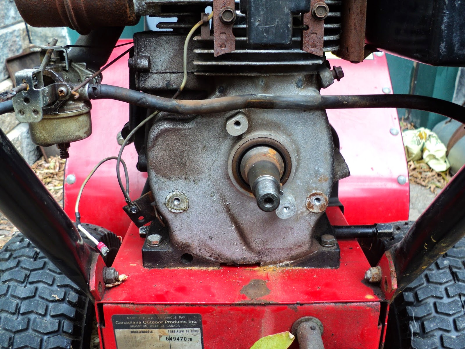
With the flywheel off, you have easy access to the retaining plate that clamps the fuel delivery tube in place.


Two 3/8" hex head screws hold the plate in place. Remove those and the plate, and nothing is in the way of  replacing the tubing run.

The short, vertical length of tubing from the tank to the shut-off valve is 1 1/2" long. The long, horizontal length of tubing is 14" long.

The tubing is a snug fit at all the nipples, but it's especially snug on the fuel tank's outlet nipple. A little WD-40 on the nipples makes the tubing easier to install.

# # #


# # #

Sunday, October 19, 2014

Just For The Heck Of It, Let's See What's Inside


The power supply in my wife's desktop PC died recently. Here's a view of the corpse.


Decades ago, one could earn a living by repairing things like computer power supplies. Outright replacement cost of such items was fairly high, so it was worth a man's while to be conversant with their innards, and equipped to diagnose and correct their failures.

Those days are long gone. Replacement cost is now so low that it's not worth a man's time to take the cover off such a thing for a look inside. But, since my time is worth nothing, I can pursue futility all day long if I choose to, so let's take a peek.


Hmmm. It's a wonder to me that a thing of such complexity can be manufactured and retailed for about $30.00 CDN. I couldn't purchase a small fraction of its components for $30.00.

It doesn't photograph well, but there's evidence of one transistor that's blown its top, and other nearby items that are scorched.


So there we are -- one more addition to the landfill site or the scrapyard, and China can sell one more new power supply. The wheels of commerce still turn, but they roll right by the likes of me. So it goes.

# # #


# # #

Thursday, September 25, 2014

Roadside Find -- A Marble Disc


My wife today found this exquisite marble disc by the side of the road.


It's 15" in diameter and 5/8" thick. It weighs almost 11 lbs.

The only bad news is that the underside features a disgusting puddle of hardened adhesive of some sort, like so.


Hmmm. I'll have to see what, if anything, will remove that mess.

- - -

Paring with a sharp utility knife blade got most of it. Lacquer thinner seems to dissolve what's left, albeit slowly. Here's my progress so far.


At least it's fit to be the disc's underside now.

- - -

I have no idea what I'm going to do with this item, but it begs me to find something very good to do with it.

To be continued, God only knows when.

# # #


# # #

Thursday, September 18, 2014

A Flowerpot Coaster


My wife has an indoor flowerpot that needs a non-scratch treatment for its bottom. The pot is very nice, but it's not something that can be safely placed on top of a finished surface -- it's liable to scratch what's underneath it. Here's a view of the flowerpot.


Underneath, there's a narrow 'rim' that's the problem.


A wooden disc 'coaster' would be a good solution, and it might make for an interesting bit of faceplate work on the wood lathe.

I have a rectangle of 9/16" thick particleboard that's big enough.


Particleboard is probably the worst possible material I could select for this, but that's reason enough to go ahead and try it anyway. Everything in life is ultimately just an experiment, so I'll experiment with particleboard here as a flowerpot coaster material.

First up is to cut that rectangle into a rough disc with a jigsaw, then mount it on a faceplate.

- - -

And here's that much done.


Now I can see what it's like to turn a true, rounded-over edge on that piece of trash material.

- - -

It can be done.


It takes a sharp gouge, presented to the work at a steep angle. You don't get shavings -- you get dust. The porosity at the centre of the material's thickness is awful.

And as long as I'm experimenting here, I may as well experiment with filler for the porosity. Here's the disc after a liberal application of Bondo glazing & spot putty.


I've been meaning to try out Bondo as a woodworking filler in places where it will get painted over, and this will be an ideal trial.

- - -

After hardening and sanding, the Bondo appears to have served remarkably well.


The Bondo did quite a nice job of filling the particleboard's edge porosity.

I'll see this through to completion with primer and paint, and I should have a perfectly good flowerpot coaster to show for it.

- - -

Update -- THURSDAY, SEPTEMBER 18, 2014

After primer and two coats of flat black enamel, here's what I've got.


It's not quite flawless, but it's close. I missed some tiny spots with the Bondo that don't show in the photograph. All in all, I'm quite pleased with the results I got from the Bondo -- it gave me a presentable, useable coaster from a piece of utter trash material.

The coaster fits the underside of the flowerpot nicely.


And it does exactly what it's supposed to do.


It keeps the hard, ceramic base rim of the flowerpot up off a surface, almost invisibly.

# # #

FEEDBACK

# # #

Sunday, September 14, 2014

Gas Water Heater TCO (Thermal Cut-Off) Trouble


Pictured above is a typical gas water heater's TCO (Thermal Cut-Off), where it resides on the heater's combustion chamber wall. (The TCO's two wire connections have been removed in the photo.) The TCO is there as a safety feature -- in the event of an over-heat condition in the water heater's combustion chamber, the TCO will go open, disabling the burner and the pilot light.

A defective TCO that goes open for no good reason will cause a very deceptive trouble symptom to arise; i.e. the pilot light will be disabled. You'll still be able to relight the pilot light, but the pilot light won't stay lit -- exactly the same symptom you'd expect from a bad thermocouple.

A continuity test with an ohmmeter will not necessarily reveal the fault in the TCO. The TCO may check out ok with an ohmmeter applied to it, but fail intermittently while in service nonetheless. To be absolutely, positively certain whether or not you have a TCO fault, bypass the TCO altogether with a splice connector, like so.


If the water heater works reliably with the TCO bypassed, you'll know that the TCO is at fault, not the thermocouple.

The TCO in the above photographs gave me exactly the trouble I've just outlined. One of its spade terminals is a little bit wiggly; that may be the cause of its intermittent, deceptive behaviour. Here's a close-up view of the thing.


The spade terminal at the unit's upper right is the wiggly one. I may be able to repair that with a hammer and punch. If not, I'll have to obtain a replacement.

In any event, I've saved myself a costly service call, and the water heater is back in business for the time being with its TCO bypassed. I'll take my chances with the safety feature's absence.

# # #


# # #

Friday, September 12, 2014

A VOM (Volt-Ohm-Milliammeter) Repair


I occasionally leave my brain in 'Park', while the rest of me engages 'Drive'; stripped gears are liable to ensue.

For example, I was using this old VOM (Volt-Ohm-Milliammeter) for something-or-other, and I neglected to mind the range switch as I went from measuring a resistance, to checking AC line voltage.


Applying AC line voltage to a VOM that's set for resistance measurement has an unfortunate effect on the instrument -- it renders the affected resistance range inoperative and, in this case, it took out the custom-made battery-eliminator/power-supply that I had designed for the thing long ago.

Fortunately, repair was not difficult once I'd obtained an ancient IC (Integrated Circuit) off of Ebay. The IC is a 723 voltage regulator dating back to the early 1970s, when I was an electronics engineering technology student at DeVry. Here's a view of the power supply's innards.


And here's a close-up of the affected IC.


I'm glad I chose to mount that IC in a socket.

With a new IC in place, the power supply was good to go. That left me with the damage to the VOM itself to deal with.

When you apply AC line voltage to a resistance-measuring range of a VOM, you destroy a resistor pertaining to the range that was selected at the time, like so.


The resistor smokes and goes open, rendering the related resistance range of the instrument inoperative.

A replacement resistor ought to be a precision type of the exact same value, but obtaining one of those would be a bit of a costly ordeal. A quick-and-dirty solution is to just use common, spare 5% tolerance resistors in whatever combination is needed. Here, I've installed a 150 ohm resistor in series with a 10 ohm resistor to give me a 160 ohm 'ballpark' replacement.


That worked fine, and got me back my VOM with all of its functionality more-or-less intact.

Now, if I'll only learn to pause and check the instrument's range switch when I ought to, there won't be a recurrence of that sort of incident.

# # #


# # #

Friday, September 5, 2014

Noma Gran Prix Snow Blower -- Impeller Bearing Failure


* * *

NOTE; I was remiss here in not photographing and documenting this matter as I took the machine apart. I'll try to do a decent job of recording the reassembly. I hope the reader may still find it of some interest or use.

* * *

The old snow blower my son bought turned out to have a severely worn impeller[1] bearing.[2] Here's a view of the thing removed from the rear of the snow blower's scoop where it resides.


It's well and truly 'game over' for that bearing.

The previous owner of the snow blower had continued to use the machine with the ruined bearing in place. That had the effect of hammering down the diameter of the impeller's shaft under the inner race of the bearing. The shaft there was about 0.013" undersize from its original 7/8" diameter.

The only way to get the shaft fit for service again was to have a machinist knurl the undersize portion, to raise crests that would again fit the inner race of a bearing. Here's a view of the knurling job done.


The crests of the knurls now represent a slight oversize of 7/8" diameter. To be able to reassemble the mechanism, I'll have to file the crests down just enough to give me a sliding fit in a new bearing. I'll do that by hand on my wood lathe, using the old bearing as a reference. Here's a view of that setup.


Done. The new bearing is now a sliding fit on the knurl.


At final assembly, I'll apply some Loctite retaining compound to the knurl, so there'll be no looseness to the bearing's fit on the shaft.[3] That may be a bit of an iffy proposition, because I'll be asking quite a lot of the retaining compound -- the retaining compound may not cure in voids as large as the knurls' valleys. Should that transpire, I'll redo the assembly with CA adhesive instead of retaining compound.

Anyway, it's time to get the impeller reassembled with its gearcase and the augers.

- - -

And here's the whole auger/gearcase/impeller affair back together and ready for installation.


Tomorrow, weather permitting, I'll get all that back into the scoop along with its new bearing.

- - -

The Weather Cooperated -- SATURDAY, SEPTEMBER 6, 2014

And here's the new bearing bolted in place at the rear of the scoop.


Here's the auger/gearcase/impeller assembly stuffed back into the front of the scoop.


And here's the impeller's shaft-end in place at the rear of the scoop, awaiting its pulley.


The machine is ready for final reassembly.

- - -

All Done -- MONDAY, SEPTEMBER 8, 2014

Here's the machine back together.


And here's a closer view of the v-belt transmission.


The locomotion belt at the right has no tension adjustment. Its tension is set by its spring-loaded idler pulley.

The auger drive belt at the left is adjustable for tension -- its idler can be repositioned in a slot for optimal tension when auger drive is engaged.

From what I've seen on this machine, snow blower auger/impeller drive is a brutal, stressful job. It's an area in any used machine that's likely to need attention. All in all, I think my approach to repairing this one was sound. The proof will be in how it stands up to the coming winter's work.

- - -

Notes:

[1] "Impeller" is my term for the second stage element of a two-stage snow blower. The 'auger' is the first stage. The auger sweeps up snow and hands it off to the second stage, the 'impeller'. The rotating impeller hurls the snow up and out the chute.

[2] The bearing's description as it appears on the sales receipt from my parts dealer is, "44-053: 9648/780048 Canadiana Keyed Bearing". It's a 1640ZZ bearing with a 3/16" keyway in it's inner race. Dimensions are 7/8" bore x 2" O.D. x 9/16" thick.

[3] As it turned out, I decided against using any retaining compound or adhesive at the bearing's inner race, where it fits over the shaft.

The bearing is an easy sliding fit on its shaft, even where the shaft still has its undamaged, un-knurled surface. The fit has to be relatively loose for the sake of ease of assembly. Were it a snug fit, it would be extremely difficult to install the auger/gearcase/impeller assembly in the scoop. That's no doubt why the bearing's inner race is keyed -- so that the loose fit won't result in the shaft turning within the bearing; the keying forces the bearing to be operative, in spite of the loose fit of the shaft.

# # #


# # #