Monday, January 14, 2019

Working With Small Stuff -- 2-56 Screws


My son found this nifty old Radio Shack handheld CB transceiver.


The only problem with it is that the front cover is loose; the unit must have been dropped once -- its front cover fastenings are broken.


To make a long story short, I drilled and tapped the blind ends of the brass attachment posts so they'd take 2-56 x 5/32" screws, like so.


A couple of No. 44 holes through the front cover followed.


And here we are with a very neat repair to the loose front cover -- a pair of 2-56 hex socket head screws are now holding it in place.


Working with tiny threaded fasteners is beguiling. So far, 2-56 is the smallest size that I'm equipped for dealing with. I've ordered up some small sizes of metric taps and screws that I expect to find use for in model building. We'll see how that goes.

- - -

Update -- THURSDAY, JANUARY 17, 2019

My set of ten tiny threading taps arrived from Amazon. Here they are all queued up.


Following is a list of the sizes:
  • M1.0
  • M1.2
  • M1.4
  • M1.6
  • M1.7
  • M1.8
  • M2.0
  • M2.5
  • M3.0
  • M3.5
Hmmm. I didn't know of the existence of about half of those sizes.

# # #


# # #

A 1/2" - 13 Bolt From A Nut, A Roll-Pin And A Length Of Threaded Rod


The title of this post pretty much tells the story, but I'll elaborate.

The 'desk' where I write these posts in my workshop is a rude, crude assemblage of odds and ends that serves the purpose, though it's ugly as sin; I'll spare the reader a view of it. Holding it together so far has been a length of 1/2" - 13 threaded rod and a couple of hex nuts. The assembly had a disturbing tendency to come unscrewed little-by-little, so I thought I'd make it more secure by fashioning a hex-headed bolt from the length of threaded rod, a hex nut and a 1/8" roll pin.[1] Here's a view of the components I'll be starting with.


A centre-punch mark on one flat of the hex nut affords a beginning to the project.


I located that punch mark strictly by eye. Human vision has a remarkable gift for locating centre without the aid of measuring tools.

Here's the nut screwed onto its rod and drilled through 1/8" diameter for the roll pin.


I made a mistake there. I should have used a second nut to jam the nut-to-be-drilled in position. The drilled nut tended to drift about as the drill met the threaded rod. Not a fatal error, but something that I won't repeat in future.

Here's the 1/8" x 1" roll pin installed and fully seated on one side of the nut.


Here's the other end of the roll pin prior to cutting it down.


And here's the finished roll pin installation after cutting off and filing the protrusion.


Not too shabby. So there I have a 7 1/2" long 1/2" - 13 bolt for holding my 'desk' together.

* * *

Note:

[1] A quick-and-dirty way to accomplish the same thing is to put a nut on the end of a length of threaded rod with red threadlocker, but I was happily fixated on using a roll pin for this.

# # #


# # #

Saturday, January 12, 2019

A Worn-Out Pepper Mill


We have an old pepper mill that's been doing a pretty poor job of grinding pepper corns lately. The mill has been replaced with a new one so we can grind pepper corns reliably again. I thought I'd take a look-see at what the old mill's mechanism consists of. Here's a view of the complete old pepper mill.


The lid comes off, of course, for filling the mill with pepper corns.


That ball-nut is 10-32.

At the underside of the mill, there's what appears to be a black plastic retainer of some sort.


There's no brand name on the mechanism, just "STAINLESS STEET". Hmmm. I wonder how many times that misspelling was repeated in metal.

A bit of judicious prying gets the retainer to come out, along with the mechanism.


There's a collar affair up inside the cavity that serves as an upper-end stop for the mechanism's biasing spring.

And here we have the business end of the mill revealed.


That spring biases the rotor downward when the mill is assembled. Apart from the spring, the unit can't be further disassembled non-destructively. I can see no practicable way to restore the mill's effectiveness.

So there we are with some salvage -- a 10-32 ball-nut, a five-inch length of 3/16" square rod and a small compression spring.

# # #


# # #

Friday, January 11, 2019

Tool Review -- Busy Bee Multi-Angle Vise No. B1942


I had a soldering job to do on a very small printed circuit board, and I didn't want to have to struggle[1] with it in any clumsy, awkward fashion. I recalled that I'd seen a rather nice little vise for such work at Busy Bee, so I looked it up and found that it's on special for $29.99 CDN, from its regular price of $39.99. Needless to say, I nipped out to Busy Bee in Pickering and got one. Here's a view of the box that it comes in.


And here's the vise clamped to my workbench.


The capacity of the bench clamp is 2 1/16". The upper 'jaw' of the bench clamp has a non-marring rubber pad.

Here's a view of the vise at work on my printed circuit board repair.


The vise did exactly what I needed it to -- hold the circuit board steady while I soldered in new components. The resilient jaw pads were just what was called for.

With the jaw pads removed, the rear jaw of the vise has cross-grooves for gripping round stock.


Aside from that feature, the naked jaws are not the textured grippers that you get on a mechanic's vise -- they're smooth and slippery. That's about the only downside to the vise.

The multi-angle locking feature works as it should; the vise head absolutely, positively can be locked in place however you please to position it. Here's a view of the feature's innards.


An M8x28mm carriage bolt is the clamping/locking screw. An M6x15mm flathead screw serves as a vertical retention stop for the assembly.

And following are a few specifications:


  • Jaw width without jaw pads installed: 2 15/16".
  • Jaw width with jaw pads installed: 3 1/8".
  • Jaw opening without jaw pads installed: 2 1/16".[2]
  • Jaw opening with jaw pads installed: 1 7/8".[2]
  • Vise screw: 7/16"-14.


  • All in all, a very nice unit. I expect that I'll find many uses for it.

    * * *

    Notes:

    [1] The words 'work' and 'struggle' are not synonyms. If one is struggling instead of working, one is ill-prepared, ill-informed, ill-equipped or some combination of the three. The 'illness' needs to be dealt with.

    [2] Busy Bee variously claims a jaw opening of 2 1/2" or 2 3/4". I don't see how they can arrive at those figures; at 2 1/2", the rear jaw has come unscrewed. I specify maximum vise jaw opening with the vise screw still fully engaged by its nut.

    # # #


    # # #

    Saturday, January 5, 2019

    A Wahl 'Peanut' Hair Clipper Failure


    Someone brought me an inoperative Wahl 'Peanut' hair clipper. Here's a view of it without its cutter head.


    And here's the underside.


    Three No. 0 Phillips recess screws fasten the unit together. Here it is opened up.


    (That photo was taken after I'd done some unsoldering.)

    There's not much to the thing -- a DC motor, a bridge rectifier, an inductor[1] and a slide on/off switch that's incorporated into the printed circuit board. Here's the schematic.


    The unit had suffered a catastrophic failure of the bridge rectifier and the inductor. The two '+ side' diodes in the rectifier were dead shorts, and the inductor had blown up. Here's what was left of the inductor after unsoldering it from the circuit board.


    The motor survived. Here's a brief video of the motor running with a jury-rigged rectifier.


    The '32 mA' figure printed on the motor must be a full-load value. Running without the clipper head attached and no loading, the motor draws about 7 mA. Motor speed is about 10,200 rpm. Loading the motor with finger pressure results in a large increase in motor current, and a corresponding reduction in motor speed.

    I've ordered replacement 2W10 bridge rectifiers from Amazon. The 2W10 is a little more robust than the original W04M.
    - - -

    The Rectifiers Arrived -- THURSDAY, JANUARY 10, 2019

    The 2W10 is physically identical to the W04M.


    Here's the circuit board set up for soldering in the new rectifier and inductor.


    And the little machine went back together and is working. I can return the unit to its owner for a proper trial with the cutter head attached.

    * * *


    Note:

    [1] From what's left of the colour code bands, the inductor appears to be 150µH. Fortunately, I have spares on hand that I got from Amazon long ago.
    # # #


    # # #

    Wednesday, January 2, 2019

    A Hitachi 1/12 HP Motor -- IBM P/N 5422230


    Here's an obscure piece of gear that I found I had stashed away.


    I think it may have been for powering an IBM keypunch machine, which makes it something of a museum piece.

    The motor is not very big; frame diameter is 4 3/4". The shaft diameter is 3/8". Effective shaft length is about 1 1/16" with a setscrew flat. Rotation is CCW as viewed shaft-end-on.

    Measured no-load speed is about 1,790 rpm. Measured no-load current draw is about 2.15 A.

    There's a two-step pulley on the shaft fastened by a 1/4"-20 x 5/16" flat-point setscrew that takes a 1/8" hex key. Sheave diameters are about 1 19/32" and 1 3/32"; the larger diameter sheave is outboard. The sheaves appear to be meant for a V-belt that's 1/4" wide at the top.

    - - -

    The Starter Relay

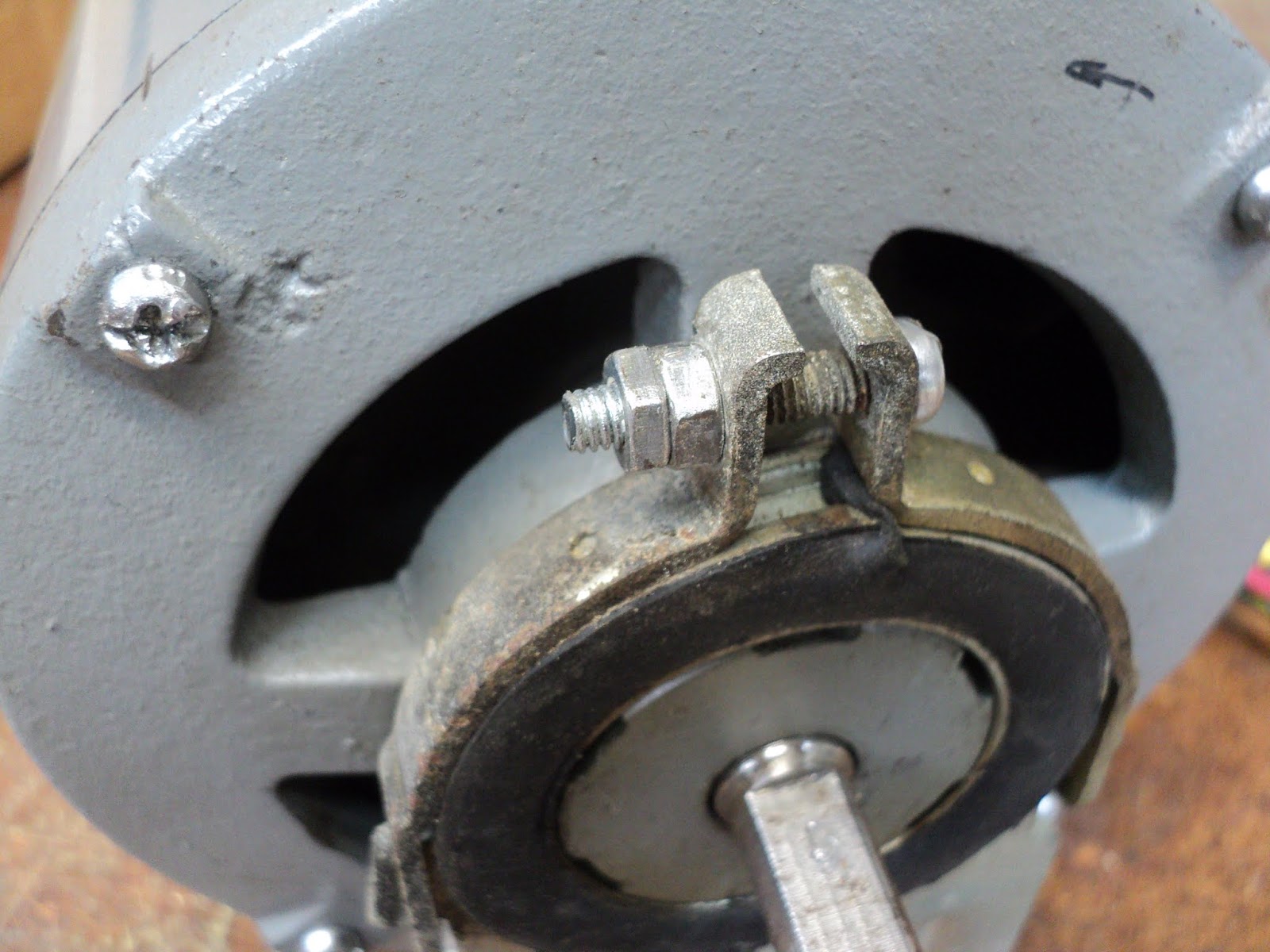
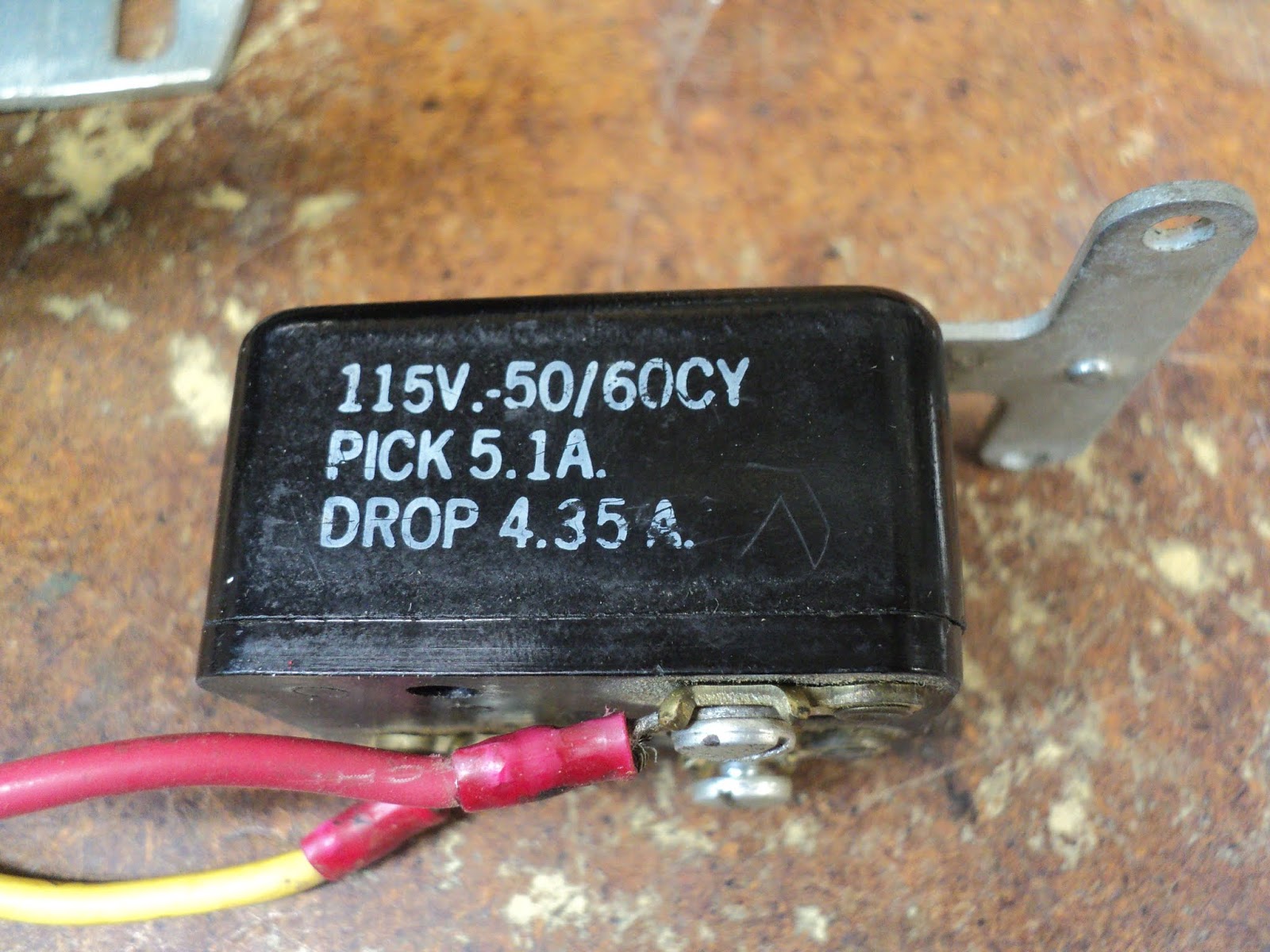
    The motor has no internal centrifugal switch for its start winding; An external relay handles start winding operation. Here are views of the sides of the relay.


    And here's a brief video showing the relay's innards in action, starting the motor.


    When I'm certain that I understand what's going on there, I'll return with an explanation.

    - - -

    A Schematic And An Explanation


    Note the following:
    • All run winding current flows through the relay's coil.
    • At power on, the run winding's inrush current energizes the relay's coil.
    • The energized relay connects the start winding to the line.
    • The motor starts. Run winding current falls off to its normal level -- a current insufficient to keep the relay energized.
    • The relay's contacts open. The start winding is de-energized and normal motor operation carries on.
    • The motor's direction of rotation can be reversed by swapping the motor's red and black leads.
    - - -
    Motor Mount -- THURSDAY, JANUARY 3, 2019

    Hitachi Made good and sure that the motor mount wouldn't come loose.


    The screws' nuts have jam nuts,[1] and the fastening is enamelled to preclude loosening. Getting that apart was a bit of a chore.


    The screws are M4x20mm. The hex nuts are 7mm A/F. Note that the cradle's longer end goes to the rear of the motor. The shock mounts are very tightly fitted onto the end-bells; I'll just leave them in place.

    - - -

    Dismantling The Motor

    A good practice when dismantling any motor is to scribe end-bell/frame alignment marks with a thin cutoff wheel in a hand grinder.


    Those marks will take the guesswork out of reassembly; you can get the motor back together exactly as the factory had it.

    A Snag

    The cross-slot/Phillips-head tie-rods holding the motor together would not break away; they seemed to be absolutely seized. I almost reamed out two heads in trying. A pair of 4" Vise-Grips applied to the heads saved the day, and I got all four tie-rods out without further damage. The tie-rods are M4x120mm. Here's a view of them.


    I've never run into such a thing before on a motor.

    Anyway, the end-bells came off with a lot of judicious hammering and prying; the bearings' outer races are quite a snug fit in their cavities. Here we are with the motor apart.


    The bearings are NSK 6201V (32mm O.D. x 12mm bore x 10mm wide; sealed both sides) -- both in excellent condition. There's a wavy spring washer in the front bearing's cavity for axial biasing.

    The stator has 24 segments; the rotor has 34 segments. I'd love to know what the ratio between the two means.

    I'll clean everything up, then I'll get to see what sort of ordeal it will be to get the thing back together.

    - - -

    All Done

    The motor is back together and working fine.


    The bearings slipped back into their cavities easily; I was getting faked out at disassembly by slight misalignment as I was removing the end-bells.

    Now if only I had a use for the thing.

    * * *

    Note:

    [1] At reassembly, I noticed that there are two different thicknesses of nut. The main tightening nuts are 3mm thick; the jam nuts are 2.5mm thick.


    Talk about 'attention to detail' on Hitachi's part.

    # # #

    # # #

    Tuesday, January 1, 2019

    A Dayton 3M029 Motor


    I have an old Dayton fan-duty motor on hand that I can't think of a use for. Also, I'm going half out of my mind for want of any engaging work to do. So, I'll dismantle the Dayton motor to see what I can learn of its construction. Maybe a use for it will occur to me.

    Here's a view of the motor.


    The motor is not very big; frame diameter is five inches. The shaft diameter is 1/2". Effective shaft length is 2 3/8", with a 1 1/2" long setscrew flat. Rotation is CCW as viewed shaft-end-on. Stator winding DC resistance is 4.3 ohms.

    Here's a view of the motor's ID label.


    Measured no-load speed is about 1,175 rpm. Measured no-load current is about 1.75 A. And with that data out of the way, let's get on with dismantling the unit.

    Motor Out Of Mounting Cradle

    Two pry-off clips come away to release the motor from its cradle.


    Note the ground continuity braid that bonds[1] the motor's frame to the cradle.

    Shock-Mounts Off


    The mounts' rubber portions protrude on one side. The protrusion sides of the mounts go inboard to the motor.

    - -

    Motor Dismantled -- WEDNESDAY, JANUARY 2, 2019


    Three 10-32 x 4" roundhead screws with 3/8" A/F hex nuts hold the assembly together. There are no washers. The screws' head ends go at the wiring end of the motor.

    At each end of the rotor, there are two axial spacers, and a thrust washer arrangement consisting of steel/felt wick/steel.


    A large oil wick surrounds each sleeve bearing.


    Shaded Pole Nature-Of-The-Beast Revealed

    This is a 'shaded pole' motor. This Wikipedia entry gives a brief introduction to the subject of shaded pole motors. This reference item from the Wikipedia entry is more detailed and quite good.

    Here's a close-up of the stator's construction that reveals the shading coils.


    They're not easy to make out, but each segment of the stator[2] has a single, heavy gauge shading winding that serves to create a phase shifted magnetic field to start the motor.

    Direction of rotation is determined by the physical position of the shading coils in their segments. This motor could be reversed, but not electrically as split-phase induction motors can be. To reverse this motor, the stator would have to be flipped around 180 degrees. (And a new hole for the input wires would have to be drilled in the front end-bell.)

    So there we have the architecture of the motor. And last but not least, there's a presumably self-resetting thermal protection device tucked away in the bottom of the stator.


    Reversing The Motor

    Just for the sheer heck of it, I may try reversing the motor.

    - - -

    Reversal Works

    I drilled a 3/8" hole in the front bell-end for the wiring, and assembled the motor with the stator flipped around. I've now got CW rotation, like so.


    So there we have the Dayton 3M029. I still haven't thought of a use for it.

    * * *

    Notes:

    [1] 'Bonds' here means 'assures electrical continuity between parts that are meant to be grounded (earthed)'. For possibly more than you ever wanted to know about bonding, grounding and earthing, see this.

    [2] The stator has six segments; the rotor has thirty-three segments. How that works out to give the motor its characteristic speed is beyond me.

    # # #


    # # #