Here's an obscure piece of gear that I found I had stashed away.
I think it may have been for powering an IBM keypunch machine, which makes it something of a museum piece.
The motor is not very big; frame diameter is 4 3/4". The shaft diameter is 3/8". Effective shaft length is about 1 1/16" with a setscrew flat. Rotation is CCW as viewed shaft-end-on.
Measured no-load speed is about 1,790 rpm. Measured no-load current draw is about 2.15 A.
There's a two-step pulley on the shaft fastened by a 1/4"-20 x 5/16" flat-point setscrew that takes a 1/8" hex key. Sheave diameters are about 1 19/32" and 1 3/32"; the larger diameter sheave is outboard. The sheaves appear to be meant for a V-belt that's 1/4" wide at the top.
- - -
The Starter Relay
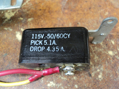
The motor has no internal centrifugal switch for its start winding; An external relay handles start winding operation. Here are views of the sides of the relay.
And here's a brief video showing the relay's innards in action, starting the motor.
When I'm certain that I understand what's going on there, I'll return with an explanation.
- - -
A Schematic And An Explanation
Note the following:
- All run winding current flows through the relay's coil.
- At power on, the run winding's inrush current energizes the relay's coil.
- The energized relay connects the start winding to the line.
- The motor starts. Run winding current falls off to its normal level -- a current insufficient to keep the relay energized.
- The relay's contacts open. The start winding is de-energized and normal motor operation carries on.
- The motor's direction of rotation can be reversed by swapping the motor's red and black leads.
- - -
Hitachi Made good and sure that the motor mount wouldn't come loose.
The screws' nuts have jam nuts,[1] and the fastening is enamelled to preclude loosening. Getting that apart was a bit of a chore.
The screws are M4x20mm. The hex nuts are 7mm A/F. Note that the cradle's longer end goes to the rear of the motor. The shock mounts are very tightly fitted onto the end-bells; I'll just leave them in place.
- - -
Dismantling The Motor
A good practice when dismantling any motor is to scribe end-bell/frame alignment marks with a thin cutoff wheel in a hand grinder.
Those marks will take the guesswork out of reassembly; you can get the motor back together exactly as the factory had it.
A Snag
The cross-slot/Phillips-head tie-rods holding the motor together would not break away; they seemed to be absolutely seized. I almost reamed out two heads in trying. A pair of 4" Vise-Grips applied to the heads saved the day, and I got all four tie-rods out without further damage. The tie-rods are M4x120mm. Here's a view of them.
I've never run into such a thing before on a motor.
Anyway, the end-bells came off with a lot of judicious hammering and prying; the bearings' outer races are quite a snug fit in their cavities. Here we are with the motor apart.
The bearings are NSK 6201V (32mm O.D. x 12mm bore x 10mm wide; sealed both sides) -- both in excellent condition. There's a wavy spring washer in the front bearing's cavity for axial biasing.
The stator has 24 segments; the rotor has 34 segments. I'd love to know what the ratio between the two means.
I'll clean everything up, then I'll get to see what sort of ordeal it will be to get the thing back together.
- - -
All Done
The motor is back together and working fine.
The bearings slipped back into their cavities easily; I was getting faked out at disassembly by slight misalignment as I was removing the end-bells.
Now if only I had a use for the thing.
* * *
Note:
[1] At reassembly, I noticed that there are two different thicknesses of nut. The main tightening nuts are 3mm thick; the jam nuts are 2.5mm thick.
Talk about 'attention to detail' on Hitachi's part.
# # #
# # #


No comments:
Post a Comment