Saturday, November 27, 2010

Uneconomical to Repair

How many times have you heard that phrase?

Every so often, I come up against an 'uneconomical to repair' item, and just for the sheer heck of it I say, "Bleep economics. I'm going to repair it anyway." This is a 'business-and-commerce-free' zone, after all, and I can adhere to my own notions of economy, warped though they may be. (Plus, I can't let a challenge like this go unanswered.)

- - -

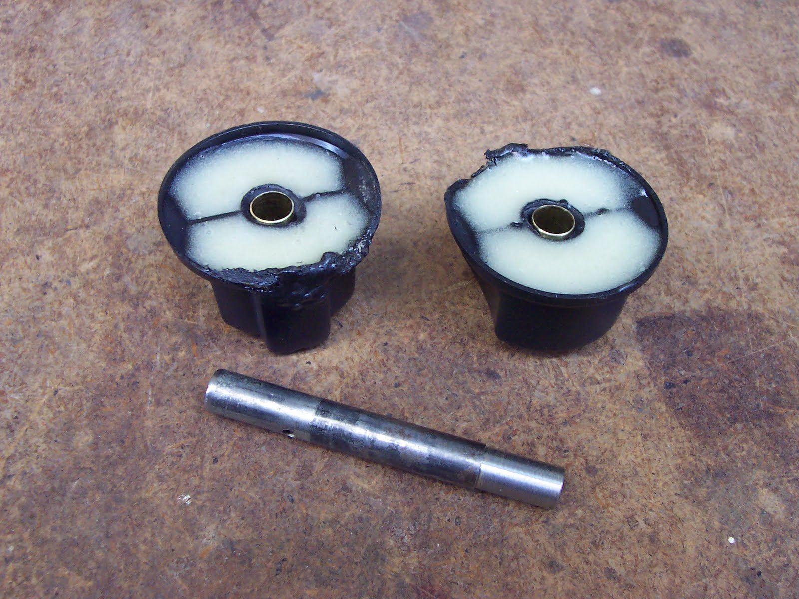
Pictured are the valve knobs from my barbeque. They've seen better days. The story of how they got to be in the state they're in is here.

Also in the shot is a length of 3/8" diameter hard brass tubing from the hobby shop that's going to figure in this.

First thing to be done is to wash away all the spider silk and grime from the things. Then I'll fill them with epoxy to lend them sufficient substance for what I have in mind.

- - -

Here's a knob all cleaned up and epoxy-filled.

That central hole that used to fit over the valve stem is badly distorted. I have to bore it out to 3/8" diameter so I can sleeve it with the brass tubing. Then I'll have to add a set screw to secure the knob, since I'll have lost the flat that used to key the knob to the valve stem. Permit me to digress here to speak of brass tubing for a bit.

- - -

That length of tubing pictured above is one size out of a whole sequence of sizes from 1/16" diameter up to, I think, 5/8". (The manufacturer, K & S Engineering, has a web site that's a bit shy on product data. I couldn't find a listing of all the available sizes.)

The tubing's sizes go up in increments of 1/32". The wall thickness is 0.014", so each size of tubing 'telescopes' into the next size up. The valve stems on my barbeque are 11/32" diameter, so the 3/8" outside diameter brass tubing (just over 11/32" inside diameter) will fit them perfectly as a sleeve.

(As an aside, a supply of the full range of telescoping brass tubing sizes is a huge asset in the workshop. The stuff is incredibly useful and versatile.)

- - -

Boring out the knob's hole to 3/8" diameter will be a bit tricky. Several things are at work here to complicate the task:

a: The knob's shape doesn't lend itself to easily aligning squarely with the jaws of my drill press vise, or to being securely gripped.

b: The hole to be enlarged is irregular. A drill entering it will tend to be deflected oddly, and chatter and chew as it's starting in.

c: Twist drills are not rigid milling cutters. They're remarkably flexible things.

To deal with the last of those three items, I modified a worn-out 3/8" drill as in the following photo:

I cut it short and reground it. I did the cutting with a 1 1/4" diameter reinforced Dremel cut-off wheel. It was not easy to cut. High speed steel is hard stuff.

The result is not an ideal drill. A twist drill's web gets quite thick up the length of it, so this would not be an easy-drilling drill. But the thick web won't be in play here since I'm only enlarging an existing hole. At least I'll have a more rigid drill.

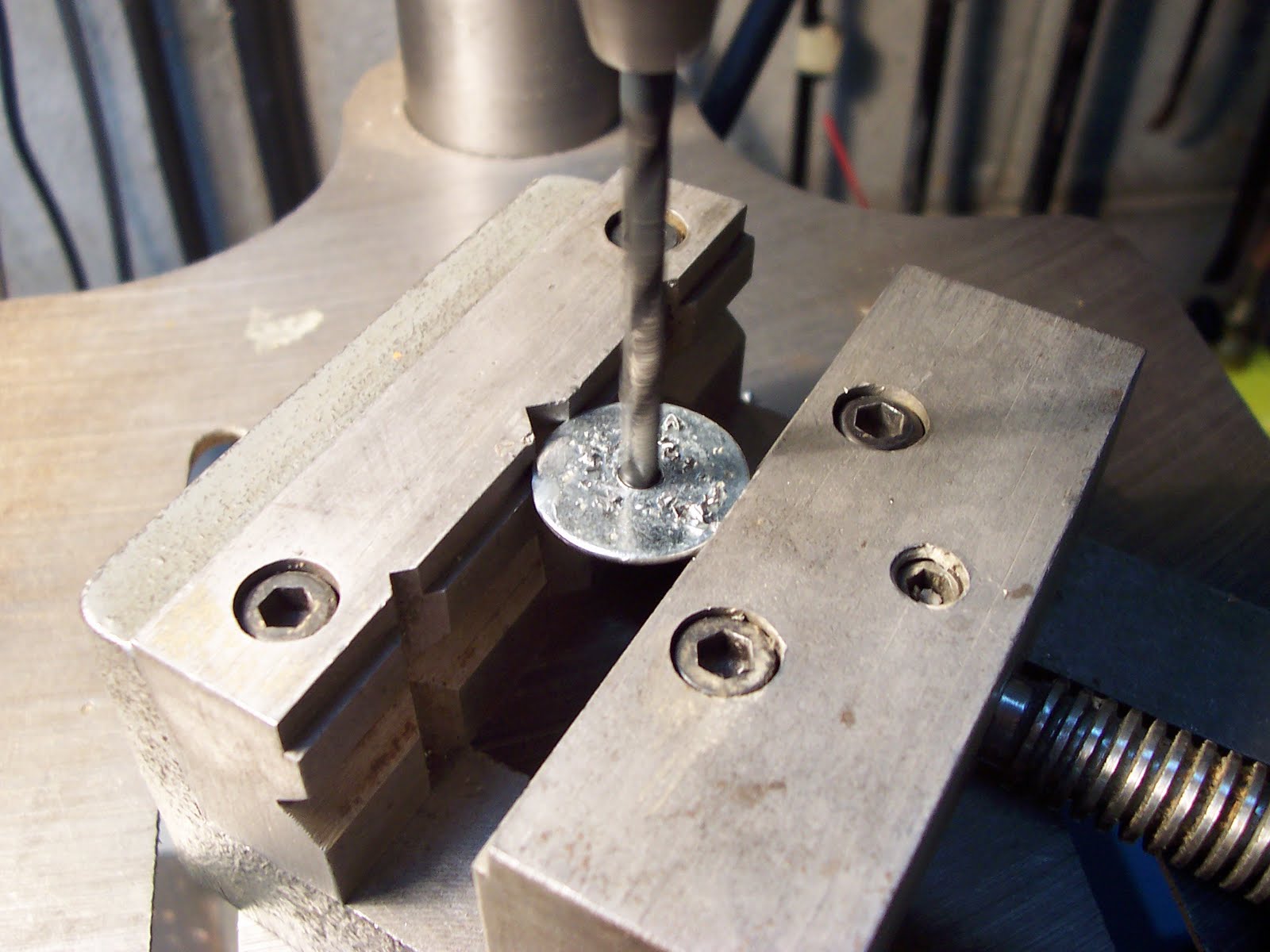
Some inner tube rubber helped with getting a good grip on the knob with the vise. Here it is set up and in progress.

It was a devil of a thing to get centred up. To help with that, I chucked a piece of 3/8" diameter tubing in place of the drill at first. That gave me a representative reference cylinder that was helpful for getting the work positioned.

It turned out remarkably well, and with a bonus -- the finished hole diameter was slightly undersize of 3/8", so I had an interference fit for the tubing. I must point out something about twist drills here.

Twist drills are not reamers. When a twist drill is used to enlarge a hole, the resulting hole will likely be slightly undersize. The effect is more pronounced in material that has some resilience to it, as was the case here. The effect can present a problem at times, but it can also be helpful when you're seeking a snug fit. In this instance, the effect gave me just the interference fit I needed. Here are the knobs with their brass sleeves installed.

In the foreground is a sleeve installation tool I made on the lathe from a scrap of 3/8" diameter steel rod. A very nice job, if I do say so myself.

In the next photo are the finished knobs in place on their valve stems.

I made two 10-24 x 1/2" set screws from the ends of regular screws. A relatively large, coarse thread like 10-24 was called for here because of the relatively soft material involved.

So, the barbeque can be back in business come spring; I just have to deal with the damaged paint on the control panel yet.

I like this sort of outcome, where no business and commerce whatsoever needed to be conducted to arrive at it.

- - -

Update -- TUESDAY, OCTOBER 13, 2015

It's happened again -- another BBQ flashback. The damage doesn't look quite so bad this time.


We'll see how well my repaired knobs stood up to this latest incident.

# # #

FEEDBACK

# # #

Barbeque Flashback Prevention

Nothing to be afraid of, unless you're about to light the barbeque.

- - -

My home is near an undeveloped river valley, and the spider population around here is huge. I'd never seen so many of the creatures until I moved here. It's no place for an arachnophobe.

For the most part, spiders and I get along fine; they really don't bother me. But they get into the fuel supply tubes of barbeque burners and make little installations of silk that impede the flow of gas. The burners can still be lit, but the flame is weak. If not noticed and left unattended, the sluggishly flowing gas will ignite back through the supply tubes and you'll soon have flames all the way back to the control valves -- not a good thing to have going on.

It happened here near the end of last season, and left me with damaged paint on my barbeque's control panel, and two distorted plastic control valve knobs.

Anyway, the lesson is 'pay attention to the flame when you light a barbeque.' If it doesn't come up blue and energetic-looking, but orange and wispy, shut it off and clean out the tubes. You'll save yourself some aggravation. (I suspect that whenever you hear of a nasty incident with a backyard barbeque, odds are it was brought on by spider silk blockage.)

- - -

Spider silk is tenacious stuff, and even a blast from a compressed air blow gun can't be relied upon to clear it out of a burner's supply tubes thoroughly. Pictured below is the best thing I've come up with so far to use as a 'brush'.

It's a length of eight-conductor computer networking cable with an inch of its jacket stripped off one end so the wires can be presented as 'bristles'. It's flexible enough to negotiate curves in the tubes, yet stiff enough that you can reliably shove it all the way through. After a reaming with the 'brush', I still follow up with a blast of compressed air.

I put the crimp terminal on the other end to secure the jacket from sliding off the wires within, and so I can hang the thing on a nail when it's not in use.

One last thing I should mention is that there's no such thing as a reliable interval between cleanings. You can clean the tubes at three on a Saturday afternoon, and they can be blocked up again when you go to light it at six. Or they might stay clear for weeks before some eight-legged little busybody gets in again. "You never can tell with spiders", to paraphrase Winnie the Pooh.

- - -

Addendum -- THURSDAY, JUNE 16, 2011

The repair job I did on the distorted knobs is here.

There's a post here about barbeque fuel delivery tubing and valves.

- - -

Addendum II -- SATURDAY, OCTOBER 8, 2011

This time of year seems to be when the spiders are most inclined to go to work on the barbeque. (And we're enjoying some exceptionally fine weather this Thanksgiving weekend, so the barbeque is needed.) 'Went to fire it up, and the flame was pathetic. Below is a photograph of what my 'brush' dragged out of one of the burner tubes.

That bit of silk is all it takes to seriously foul up a burner's operation, with very nasty results if it's not noticed and corrected.

# # #

FEEDBACK

# # #

Sunday, November 21, 2010

Clothespin Clamps


At the top in the above photo is a common torsion-spring-type wooden clothespin. Below it is the same thing, assembled in reverse.

It gives you quite a useful little modelmaker's clamp with inherently non-marring jaws. And here are a couple of other applications.

They're also useful for holding small objects to be spray painted.


 With a bit of further modification, you can make an excellent starting holder for tiny nails out of one.


- - -

Please note that I can't claim to be the originator if this idea. I saw this done long ago -- I can't recall where.

# # #

FEEDBACK

# # #

Saturday, November 20, 2010

Winterizing a Tecumseh Lawnmower Engine

Is that a handsome piece of machinery or what?

My son and I found this mower by the side of the road some years ago. It had no spark plug or oil in it, but was otherwise intact and appeared to be worth a closer look; so onto the truck and home it went.

- - -

I looked underneath it and something looked amiss. There was a reasonably sound-looking mulching blade on it, but it had been installed upside down. One wonders if the mower's owner had a thought something like, "I just sharpened that blade and put it back on and it cuts worse than ever. To heck with it. Time for a new mower." Had he retraced his steps, he might have figured out that he'd converted his lawnmower into a lawn flogger.

In any event, I flipped the blade over, filled the sump with oil, installed a spark plug and it started and ran fine. It cut grass too. Not a bad find.

- - -

The mower has to spend winters out on the patio. I have no shed or garage to keep it in, so I've come up with a little winter-proofing regimen that's not a lot of work, and gives me very good odds of a trouble-free startup in the spring. It goes like this:

1) Remove the spark plug. Spray in some WD-40. Replace the spark plug and give the starter cord a few pulls to distribute the WD-40.

2) Remove the following items:
  • Fuel tank.
  • Air cleaner.
  • Cowl w/recoil starter. (The recoil starter's cord is best kept inside where it'll stay dry. It'll last much longer that way.)
  • Governor linkage plate w/link and spring. N.B. -- Unless you're one of those natural-born mechanics who can just intuit how things go back together, you're well advised to draw yourself a clear sketch of something like a governor linkage arrangement. It may not be obvious to you what goes where come the spring.
  • Carburettor.
3) Drain the fuel tank. Leave the cap off of it.

4) Clean all the removed items. Take the float bowl off the carburettor, clean it and leave it off.

5) Stash all the removed items together in a box.

6) Pinch the crankcase vent tube shut with a binder clip.

7) Bung up the engine's intake port with a cork. In the following photograph, that's a synthetic wine bottle cork that I've whittled down for the purpose.

8) Blow off all the accumulated grass and stuff with compressed air.

9) Spray the muffler down with WD-40. Apply WD-40 anyplace that looks like it could use it -- cable ends, pivot points, what-have-you.

And here we are. The only thing left is to slip a garbage bag over it for a cover and tie it in place. Winter can do as it pleases; the engine will be snug.

Come spring, check the carburettor's float level, reassemble everything, oil the air cleaner element, fuel it up and away you go.

I didn't mention changing the oil. I really should have done that first here, but I was too lazy to. I'll do it first thing in the spring.

# # #

FEEDBACK

# # #

Saturday, November 13, 2010

An Aid to Lamination

With the price of material what it is, I'm inclined to use lamination and biscuit joinery whenever and wherever possible to build up scraps and salvage into usable stock.

A difficulty that often arises when gluing up a lamination is that the wet glued interface(s) want(s) to slip-slide away as you clamp the thing up -- you can't keep things aligned as they're meant to be. A way to eliminate that problem is to install dowels clear through the assembly to act as alignment pins. Here's a photo of an assembly that I've readied for gluing.

One dowel is shown partially inserted. There's another hole for a dowel at the other end of this two-foot long assembly. The dowels are located in what will end up being waste. (This is going to be the central spire for an angular, four-legged garden trellis.)

Make the dowels just a bit shorter than the total thickness of the lamination, so they can be set to just below flush at both ends, and won't interfere with any sawing operations to come.

Before I take this out of the vise to apply the glue, I'll mark the edges of the three pieces so I can't lose their present relationship. There's no way I got those two holes drilled perfectly symmetrically and perpendicularly; this will have to go back together exactly as it is now.

Undersize Dowel

This technique works best with snug-fitting dowels, but a lot of dowel stock that's sold is slightly undersize. I find it rare to ever obtain true-sized lengths of dowel. (Fluted dowel pins intended specifically for dowel joinery don't share that defect. I find them to be reliably true-sized.) I used 1/4" diameter dowel here and sure enough, the dowel stock I had on hand was a bit undersize.

Twist drills have a characteristic you can exploit to improve the fit of undersize dowel. A twist drill is not a reamer. When a twist drill's centre tip (the 'web') is unsupported by solid material, as is the case when enlarging a pre-existing hole, the resulting hole will be ever-so-slightly undersize. The effect is very slight, but it's enough to be helpful when fitting undersize dowel stock.

When I drilled those two holes, I first used a 15/64" drill, then followed up with a 1/4" drill. It gave me quite a good, snug fit for the dowels.

Here's the glued up, clamped up assembly back in the vise with its alignment dowels fully in place, just below flush.

I wasn't concerned here with protecting the material from jaw marks; this lamination is going to get a lot of resawing done to it before it's finished.

The job went quite smoothly. With the dowels maintaining alignment, I was able to just go through the requisite motions with nothing drifting out of place on me. This time tomorrow, I'll have the piece I need for that trellis' spire.

# # #

FEEDBACK

# # #

Saturday, November 6, 2010

Truing a Portable Circular Saw

My old Sears Craftsman portable circular saw is a tool that I seldom use; I don't do much in the way of construction carpentry. When I do use it, it's often with a sawyer's straightedge clamped in place to guide it as I shorten a door or whatever. The saw's behaviour with a straightedge guide led me to take a closer look at the machine's construction. Here's a photograph of the subject saw. Note the elevation pivot point just in front of the front handlebar. That will be key to some of what's to come later.

For a saw to work properly with a straightedge, the saw's blade must be dead parallel to the edge of the saw's baseplate. If the blade is skewed slightly towards the guided edge at the front, the saw will want to forcefully cram itself against the straightedge, to the point of deflecting it. If the blade is skewed slightly away from the guided edge at the front, the saw will want to drift away from the straightedge. Either case makes for a difficult-to-guide saw.

This saw's blade is skewed towards the guided edge at the front by almost 0.5mm, so it wants to cram against the guide. Here's a slightly annotated photograph of the underside of the baseplate to help illustrate what I'm on about.

What it boils down to is that dimension 'A' ought to be exactly equal to dimension 'B'. On this saw, dimension 'B' is less than dimension 'A'. There is no adjustment provision.

That aside, what's with that concavity in the saw blade that I can see now that that paper rectangle's straight edge is up against it?

I loosened off the saw's spindle bolt, and the concavity went away. Something must not be right with the parts that clamp the blade to the spindle. Let's have a look.

On the left is the flanged bushing nearest the motor that the blade is clamped against. in the middle is the outer clamp washer that the bolt tightens down on.

The washer is undercut away from its periphery. That does make sense. The idea would be to concentrate the washer's clamping force out around its periphery, where the clamping force's moment arm is the longest.

That would have been a great idea had they followed through with the correct and obvious thing to do -- i.e. make the bushing's flange the same diameter as the washer. But they didn't do that.

The flange's diameter is smaller than the undercut washer's diameter, so it comes as no surprise at all that when tightened, the combination produces a concavity in the saw's blade on the motor side of the blade.

Here's a quick and dirty fix for that; flip the washer so its chamfered outside will face the blade.

I'll lose the good effect of the undercut, but I'll no longer have a concavity in the blade. The clamping effect of the washer should still be quite adequate.

Returning to the matter of blade/baseplate-edge parallelism, here's how I went about actually gauging it so I could determine that it was off and by how much.

That small level is a magnetic one. I placed it there to give me a crisp, dead-straight reference edge to refer to, rather than the pressed up lip of the saw's baseplate. That's the depth probe of a vernier caliper that I'm using to get the dimension. It's a delicate bit of business, but it does work to give you quite an accurate idea of a saw blade's parallelism to the baseplate's edge.

Anyway, having determined that the saw's parallelism is off, what's to be done about it? That question brings us to the elevation pivot point that I mentioned much earlier. Here's a close-up of the pivot point from above that will give us a clue.

Note the gap at the right side end (up in the photo) of the 'hinge'. I'll force the saw's body over rightward to shift the gap to the left side end.

With the gap shifted over, I remeasured the parallelism, and it was much improved. But the saw's hinge is inclined to bias itself over to the left. What's called for is a shim washer that will force the gap to be taken up at the left side.

The pivot pin, a 1/4" diameter roll pin, will have to come out and be replaced by a 1/4" - 20 bolt.

And here we are after a bit of struggle with the roll pin; it really didn't want to leave home. Also in the shot are an example of the bolt used, and the fine adjustment tool for tweaking the shim-improved parallelism to perfection. (I'm not kidding.)

That's a 2 1/2" long bolt that I cut down by 3/8" for this. That length of bolt gave me an unthreaded shank length great enough to serve as a pivot pin. To have put a full-length threaded stove bolt in there as a pivot pin would have been sinful; having things pivot or rotate on lengths of screw-thread is a poor practice.

With the shim washer in place, the parallelism was much better, but still not perfect. A couple of whacks at the appropriate corner of the baseplate with that two-pound hammer brought it as near to perfection as I ever expect to get it.

Now if I go out and buy a new blade that has all its teeth on it, I'll have a half decent saw.

# # #

FEEDBACK

# # #

Tuesday, November 2, 2010

Fender Washers

Fender washers are just flat washers with an oversize outside diameter. I imagine that the name comes from early days in the automobile industry, when cars' fenders weren't integrated with their bodies as they are on modern cars. Fenders were separate curvaceous sheet metal items that were bolted onto the corners of the body. Large diameter washers would spread out the clamping force of the bolts, and make for a more robust, fatigue-resistant attachment.

Applications for such washers crop up now and then. I've gotten the larger sizes (1/4" and up) at The Home Depot. If you save the knock-outs from electrical boxes, you'll have the makings for 7/8" diameter washers on hand. The knock-outs are suitable for screw sizes 6, 8 and 10, though they border on being a bit too large and ungainly-looking for No. 6 screws. Here's a photo, with one knock-out done as a No. 8 washer:

For rough work, you can just eyeball a centre punch position and drill the thing. For a good appearance, use a centre-finder to spot the true centre, drill a 3/32" pilot hole followed by the requisite size of drill for the screw. Deburr the hole and file off the burr that's at the edge from breaking out the knock-out.

Hole sizes are as follows:

No.6 -- 9/64"

N0. 8 -- 11/64"

N0. 10 -- 13/64"

A drill press vise makes drilling the things easy. Here's how it looks in action:

I wouldn't care to have to make 100 of the things this way, but for my usual requirement for one or a few, it's not at all impractical to do. And the price can't be beat; saves me money to spend on essential bad habits.

# # #

FEEDBACK

# # #