Here's an old-timer with everything; electric start, self-propulsion with three-speed transmission, aluminum deck -- a 1997 high-end machine now long out of production.


Model number is 10546. Serial number is 7904361. I managed to get a parts catalogue and some specifications off of Lawn-Boy's website. I even found an operator's manual here.
- - -
It has a few little issues:
- Leaky float-bowl needle valve in the carburetor?
- Hard starting.
- The battery is not OEM. It needs to have a mounting clamp fabricated for it.
- - -
Recoil Starter Removal
Release the starter cord from its keeper/guide by prying open the slot in the keeper/guide a bit with a suitable screwdriver blade
Four 10-24 x 3/8" hex head screws w/captive flat washers, 5/16" A/F.
Shroud/Fuel Tank Removal
Have the fuel tank's shut-off valve closed.
Five No. 10 x 3/4" hex washerhead threading screws, 5/16" A/F. Four of the screws are in plain sight. One of the five is tucked away underneath at the rear, directly below the fuel filler cap. There's a short tubing elbow that connects the fuel tank's outlet nipple to the carburetor. There are no clamps on it -- it's just a force fit onto its nipples. That may be part of the fuel leakage problem on this mower. The tubing came off its nipples very easily.
It looks like I could have removed the shroud with the recoil starter still on it.
Anyway, that all gets one to here, where things are pretty much accessible.

- - -
Carburetor Removal -- MONDAY, FEBRUARY 25, 2019
An obvious clip secures the air cleaner cover. Release the clip, and the air cleaner cover and foam filter element can come away, revealing two hole plugs at either side of the carburetor's throat.

(Now is a good time to check primer bulb action. Pressing the primer bulb should result in a healthy dollop of fuel being forced up out of the carburetor's main jet.)
Remove the two plugs (they pull out easily) and you have screwdriver access for the two 1/4"-20 x 3/4" screws that fasten the carburetor to the engine's crankcase (No. 3 Phillips recess). And here's the carb off the crankcase.

Note the following:
- There's a flat heat shield between the carb and the engine, with a gasket on either side of it. Note the heat shield's orientation and set it aside.
- If the inboard heat shield gasket is in good condition but stuck to the crankcase, just leave it be.
- Squeeze the throttle cable's retaining ears to free the cable from its bracket, and unhook the end of the cable from the slider.
- The governor spring on this engine is a torsion spring. Governor spring tension works to open the throttle; air vane motion works to close the throttle.

Float Bowl And Needle Valve/Seat
Four No. 8 x 5/8" filister head threading screws fasten the float bowl to the body of the carburetor (No. 2 Phillips recess). Here's the whole affair taken apart.

Note the following:
- The float looks awful, but I tried it in solvent, and it does float.
- There's no float level adjustment.
- The needle valve has a resilient tip. This one looks fine.
- - -
The Needle Valve Leaks, Alright -- WEDNESDAY, FEBRUARY 27, 2019
There's slight fuel leakage out the throat of the carburetor, so I'll replace the needle valve and seat. I'll also replace that dreadful looking float, just in case it's subpar and contributing to the leakage problem.
- - -
Carburetor Parts Obtained -- WEDNESDAY, MARCH 6, 2019
Here they are.

There we have:
- Bowl gasket.
- Needle valve, seat and clip.
- Intake gasket.
- 9/64" I.D. primer tubing.
- 1/4" I.D. fuel line tubing.
All went together well, except for the fuel line tubing. I'll have to re-use the original, pre-formed tube. The tubing length is too short for regular tubing -- it kinks when trying to make the corner that it needs to between the fuel tank and the carburetor.
- - -
High Weirdness In The Electrical System
Something is seriously wrong with this machine's electricals. I'll return to this when I have it truly figured out.
- - -
Wiring Trouble Solved -- WEDNESDAY, FEBRUARY 27, 2019
Here's a simplified schematic of the mower's wiring.

Somewhere, sometime in the past, someone had misconnected two wires. The alternator's output wire had been connected to the 'kill' terminal of the bail-operated run/kill switch, and the kill wire had been connected to the alternator's output terminal.
So, the kill function was inoperative; the engine was being stopped by the brake alone. When the run/kill bail was released, the kill switch was shorting B+ to B-, quickly draining the battery.
If nothing else, this illustrates the fact that one never knows what one may encounter on old equipment. It's a safe bet that it's been tinkered with at one time or another, to God knows what manner of effect.
- - -
The Spark Plug
Lawn-Boy's specs call for a Champion RJ12C. The plug that's in the engine is an NGK BM6A, like so.
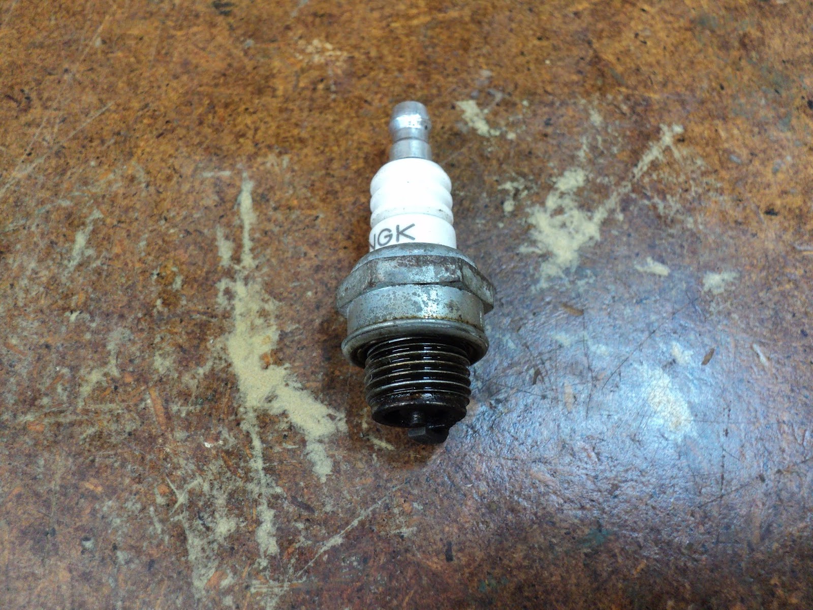
Hmmm. It's in good condition, and it does fire. The gap is way below spec. Lawn-Boy calls for a 0.035" gap. The NGK's gap is 0.018". Let's try setting the gap to 0.035", and see how that works.
- - -
Yes! A nice big healthy spark. Nonetheless, I'll replace the NGK plug with a Champion RJ12C. One deviates from OEM spec at one's peril.
- - -
New Spark Plug Obtained -- THURSDAY, FEBRUARY 28, 2019
Here's the Champion RJ12C alongside the NGK BM6A.

Two different plugs, but with the same thread and reach. The NGK is a non-resistive plug with a 3/4" hex; The Champion is a resistor type with a 13/16" hex.
Anyway, I gapped the new spark plug to 0.035" and tested it --it works. It's in the engine now, awaiting further testing of the mower.
- - -
Blade Removal -- TUESDAY, FEBRUARY 26, 2019
Here's a view of the blade.

The hex nut is a prevailing torque type, 5/8"-18, 15/16" A/F. That four-pronged affair is a mulching fan. An impact wrench gets the nut off easily. Removing the nut, mulching fan and blade gets you to here.

That rectangular piece is the blade driver. It's stuck fast on a taper. Give a corner of it a rap with a plastic-headed hammer, and it will break free of its taper.
Muffler And Exhaust Ports
With the blade driver off, you're confronted with this.

Three 5/16"-18 x 3/4" hex washerhead screws (1/2" A/F) holding the muffler in place. It seems that the muffler is supposed to be removed for periodic cleaning of the exhaust ports. I'm skeptical about that, but let's have a look.
- - -
Here's the muffler removed.

And here's a peek up into the exhaust ports.

Hmmm. Those ports look pretty clean to me. Until I see evidence to the contrary, I'm calling hogwash on exhaust port cleaning.
- - -
Rear Wheels -- WEDNESDAY, FEBRUARY 27, 2019
It's a safe bet that the rear wheel drives could stand cleaning and fresh lubricant, so let's get on with removing the left side wheel for starters, and dismantling the drive.
Under the wheel's hubcap is the 1/2" A/F hex head of the wheel's stub axle. Unscrewing that gets one to here.
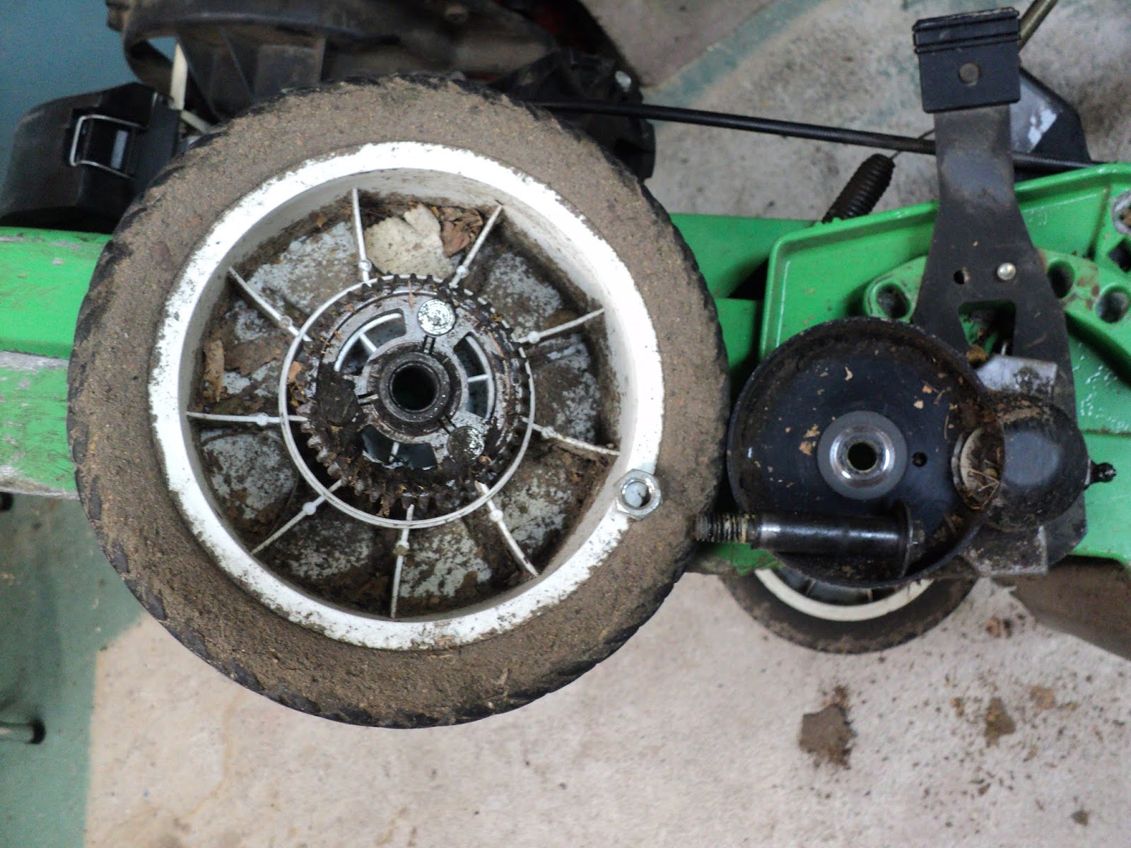
Yes indeed, plenty of dirt and dried out grease. The hex nut is a 3/8"-16 prevailing torque type, 9/16" A/F. The hex nut resides in a hexagonal cavity at the back of the wheel's height adjustment arm, so there's no need to have a wrench on it while unscrewing the stub axle. (For what it's worth, the wheel's ring gear has 43 teeth.)
I'm glad I printed out a copy of the illustrated parts breakdown for this machine, because there's quite a lot to the wheel drives. Here's a view of the drive pinion gear with the drive cover taken away.

That pinion gear's installation represents ten components arrayed on the end of the axle. Removing them all frees the wheel height adjuster, which frees the axle from the deck. Here's the illustration from Lawn-Boy's parts catalogue.

And here's a view of all the wheel drive components laid out on the bench.

The components are laid out from inboardmost (upper left) to outboardmost (lower right). Following is a list of all the items in order from inboardmost to outboardmost.
- Externally keyed thrust washer.
- Keyed thrust washer.
- Retaining clip.
- Resilient friction ring.
- Rocking key actuator w/rocking key.
- Pinion gear (15 teeth).
- Keyed thrust washer.
- Compression spring.
- Retaining clip.
- - -
Rear Axle/Transmission Removal -- THURSDAY, FEBRUARY 28, 2019
With the wheel height adjusters removed, the axle ends are free of the deck. Now it's time to unhook the self-propulsion engagement cable, free the V-belt from its pulley on top of the transmission and disconnect the shifter cable.
There's a plastic cover over top of the transmission.

The cover is fastened to the deck by two 10-24 x 1/2" hex washerhead screws (5/16" A/F). Remove those two screws, then proceed as follows:
- Unhook the self-propuslion engagement cable from its bail. Depending on the cable's tension adjustment, this may or may not be readily doable. If the cable can't be unhooked from its bail, unfasten the cable's bracket from the deck.
- Unhook the self-propulsion engagement cable from its lever down below.
- Take away the transmission cover.
That gets you to here.

Note the two 3/8" A/F hex washerheads. Those are the heads of two 1/4"-20 x 1 1/4" screws that fasten the engagement lever to the transmission. There are two 1/2" long spacers associated with the screws underneath the lever. Remove the screws, lever and spacers. The V-belt can be freed from its pulley.
Remove the 1/8" x 3/4" cotter pin from the shift lever's shaft, and pry off the shift lever. Force the shifter cable end out of place and disconnect it from its bracket. The rear axle/transmission unit is free to come out. Here it is up on the bench.

At the long right side axle, remove and clean the sleeve, a steel washer and a felt washer.
Gearbox Bottom Cover Removal
Six hex washerhead 1/4"-20 x 3/4" thread rolling screws (3/8" A/F). Here's a view of the opened gearbox.

That looks fine, actually. The grease is well distributed and not dry. What I consider to be hard shifting may just be the nature of the beast -- not something that can be 'corrected'.
So at this point, one must ask oneself, "Should I let discretion be the better part of valour and just button the thing back up?"
- - -
Hmmm.
- - -
Oh, what the hey; why not? Let's go ahead and tear the thing down, clean it and reassemble it with fresh grease. We might learn something.
- - -
Gearbox Disassembly -- FRIDAY, MARCH 1, 2019Here's the illustration from Lawn-Boy's parts catalogue.

- - -
Ok. I've dismantled the intermediate shaft and the axle and cleaned all the components, which brings me to here.

There's the axle with its right side bearing still on it. The gear sleeve is still there as well, pinned to the axle. There's no compelling reason to unpin it, so I'll just leave that be.
The bearing should come off to have its bore properly cleaned, but the axle is rusty and the bearing won't slide off.. I'll brush the axle on my wire wheel machine and get the bearing off for cleaning.
- - -
Done. And that leaves me with a filthy gear case with its input pulley, bearing and gear still in place.

I can't permit the bearing to be immersed in solvent, but to dismantle the input shaft components and press out the bearing might be folly. So, I'll clean up the gear case as best I can without wetting the bearing with solvent. Then I can reassemble the unit with fresh grease.
- - -
Hmmm.
- - -
Oh, what the hey. I've come this far; I may as well go the whole nine yards.
- - -
And here are the gear case's input components.

From left to right we have:
- Ball bearing. As near as I can make out its tiny markings, it's an SKF 6203-2RS; 17mm bore x 40mm O.D. x 12mm width, sealed both sides.
- Input bevel gear/spindle (12 tooth gear).
- Spacer and two pulley halves.
- Flat washer.
- 3/8"-24 nyloc hex nut (9/16" A/F).
- - -
A Kinked Cable
I don't like the looks of this.

Pictured above is the lower end termination of the self-propulsion control cable's sleeve. The cable's jacket has fractured, and the cable is meeting its terminator at a severe angle -- that's stressful for the wound-steel sleeve of the cable.
I came up with a neat fix for that using a 1/4"-20 coupling nut and a couple of small hose clamps.
I bored through a coupling nut 7/32" (cable jacket diameter), then half way through 19/64" (approximate terminator diameter). Then I sawed the coupling nut in two lengthwise. That got me these two pieces.

I clamped those onto the terminator/cable-jacket junction like so.

And now I have a nice, straight, stress-relieved cable sleeve termination. The cable moves freely in its sleeve, as it ought to. That may last indefinitely.
- - -
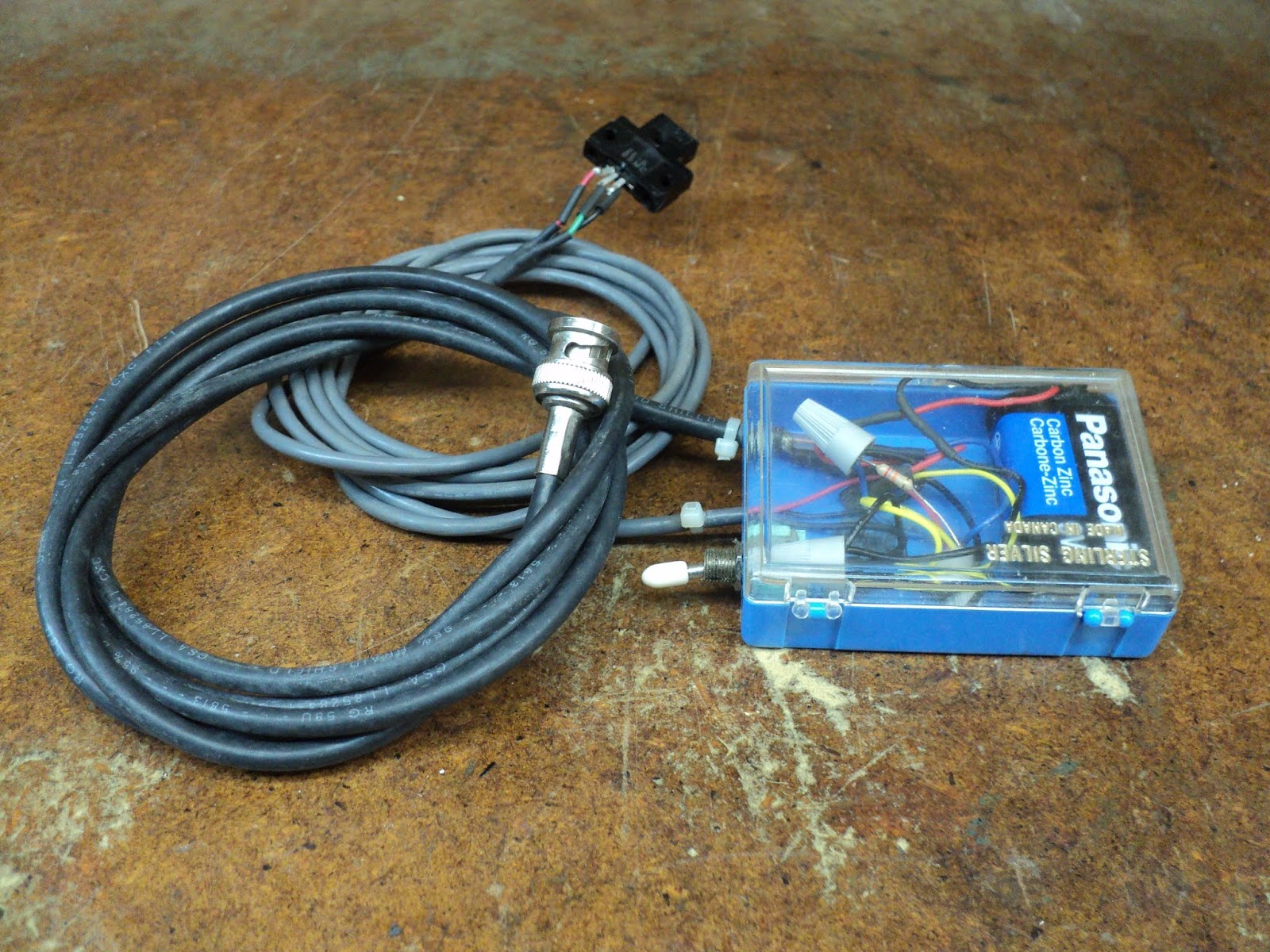
Battery Clamp -- SUNDAY, MARCH 3, 2019
The original battery and battery housing were missing from the mower; a 5Ah rectangular sealed lead-acid battery has been substituted. The substitute battery affords no really good way to clamp it in place. The best I could come up with was this.

That's a length of 3/4" All-Round galvanized strapping, fastened with two 10-24 screws in the original battery housing mounting screw locations. It remains to be seen how well that scheme holds up.
- - -
Uh-Oh -- SATURDAY, MARCH 16, 2019
I had the engine running for a few minutes today when I took the machine outside, to free up some space in my workshop. The battery exhibited a tendency to 'walk' off to one side under its restraining strap.
I did a quick-and-dirty fabrication job to come up with a side-to-side restraint for the battery.

Maybe that will finally do the job right.
- - -
All Done -- WEDNESDAY, MARCH 6, 2019
I took the room temperature machine outside where it's minus three degrees Celsius (26.6 degrees Fahrenheit). With the recommended three primes it started on the first pull, ran for a few seconds then died. One more prime and one more pull got it running again, and it kept running. The battery appears to be taking a charge from the alternator. 'Nothing more to do now but wait for the weather to turn, and see how the mower performs.
- - -
One Last Touch -- SATURDAY, MARCH 9, 2019
The recoil starter's pull handle is shabby.

The handle's shank has split. A 1/2" copper pipe coupling is a snug slip fit over the shank, and closes up the split nicely.

And Another 'Last' Touch -- THURSDAY, MARCH 14, 2019
The mower's owner has inspected the machine, and he found fault with the tension of the self-propulsion bail. It seemed to him that the bail's tension is noticeably greater than it was before I added the strain relief to the cable's termination. I can't see how my strain relief addition could have affected cable tension, but I can only take the owner's perception as genuine, and proceed to adjust the self-propulsion cable's tension.
Self-propulsion cable tension adjustment has two simultaneous effects -- on V-belt drive tension and on bail tension at the handlebar. Greater V-belt drive tension results in greater bail tension, and vice versa. What's wanted is a relatively light, comfortable bail tension while still providing adequate V-belt drive tension. Here's the adjustment procedure from the Lawn-Boy Operator's Manual.

I wanted to be able to observe V-belt tension as I made the adjustment, so I went about it a little differently. Following is my procedure:
1) Unhook the self-propulsion cable from the bail lever.

2) Unhook the self-propulsion cable from the transmission's V-belt tensioning lever.

3) Remove the transmission cover (two 10-24 hex washerhead screws, 5/16" A/F), and reattach both ends of the cable. That gets you back to where you started from, but with the transmission cover out of the way of your judging V-belt tension. Now you can loosen off the two jam nuts (1/2" A/F) on the cable jacket's termination, and adjust and try effective cable length (tension) as required.

In my experience, V-belt drives don't need to be tightly tensioned in order to operate satisfactorily. The belts exhibit a 'wedging' action as they wrap around their pulleys. It's that wedging action that gives the belts traction, and the wedging action is operative even with relatively light belt tension.
Once you've struck a satisfactory balance between V-belt tension and bail tension, you can unhook both ends of the cable again, and button everything back up, good to go.
# # #
# # #