Thursday, January 31, 2019

A Sears Craftsman Cordless Rotary Tool From The 1980s


Here's a very nice rotary tool that hasn't aged very well.


It's a Model No. 572.248960 with two speeds -- 15,000 and 20,000 rpm. Nominal battery voltage is 6V. It has the smoothest-running, most perfectly balanced motor I've ever encountered in this class of machine.

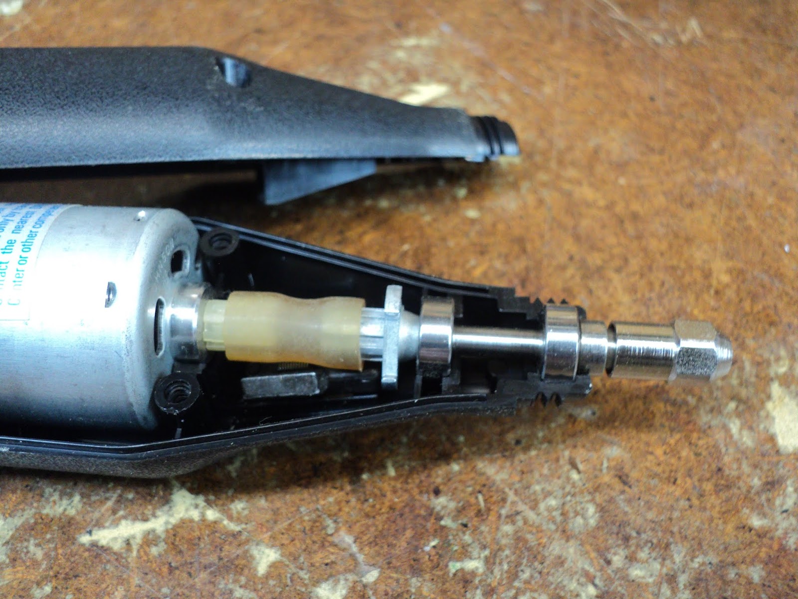
But it's old. Its Ni-Cd battery isn't holding a charge all that well, which comes as no surprise. What did surprise me was a failure in its drive-line -- a plastic flexible coupling sleeve embrittled and broke down, rendering the tool completely inoperative. Here's a view of the failure.


The outboard portion of the sleeve had fallen to pieces, which I've removed. The inboard portion of the sleeve is still there on its spline.

I removed the remainder of the flexible coupling sleeve, and went for a rummage through my stash of plastic tubing. That got me some thin-walled stuff with a 1/4" inside diameter that looked like it might serve. I cut a 7/8" length of the tubing and force-fitted it onto the driving and driven splines, like so.


'Buttoned up the casing and the tool appears to be useable now. I'll keep it in its charging stand continuously charging (the user's manual says it's alright to do that), and see if the tool makes itself useful.

# # #


# # #

Tuesday, January 29, 2019

A Toy Tow Truck's Dome Light From Patio Lantern Circuitry


I have a relic of my boyhood that resides on a shelf -- a toy tow truck with a flashing dome light.


I've made some small improvements to it over the years, most notably to the switch that operates the dome light off the front axle's rotation.

The original switch was an unreliable affair, so I bypassed it with a microswitch. Here's a view of the truck's underside where the microswitch resides.


That microswitch arrangement worked out well, but the dome light itself wanted improvement. The original dome light was a No. 112[1] incandescent bulb. The effect from it was lame. In operation, the bulb would barely get to incandescence before it got switched off again by the front axle's rotation. Some work that I'd done with solar patio lanterns led me to think that patio lantern circuitry might be applied to the problem to good effect.

I stripped down a patio lantern circuit board to its bare essentials, and installed it in the truck. I soldered the LED to the miniature screw base of a burnt-out light bulb, with the cathode connected to chassis ground. That turned out ok, and worked way better than the incandescent bulb ever did. Here's a view of the little circuit board residing inside the cab of the truck.


And here's a brief video of the dome light in action.


I know it's not great, but it's a big improvement over the incandescent.

Here's the schematic of the circuit.


Notes On The Schematic
  • Diode D1 could be omitted altogether. I just left it in place to save myself the trouble of removing it.
  • Pin 2 of the IC is the chip enable (CE) signal. That pin appears to be internally pulled down to the enabled state, so there was no need to ground the pin.
* * *

Note:

[1] The No. 112 bulb is a TL3, miniature screw base, lens-end bulb rated at 1.2 volts, 220 milliamps.

# # #


# # #

Sunday, January 27, 2019

A Toy Model T Ford From The GREAT BOOK OF WOODEN TOYS


Built from a plan in the book, "GREAT BOOK OF WOODEN TOYS" by Norm Marshall and Bill Jones.


A pretty good outcome. I've built a number of toys from the above cited book, and they've all turned out ok.

Mr. Marshall was a brilliant designer; all of the toys in the book are exquisite toy caricatures of the real things. That said, I have a few issues with the book.

First off, the book's front cover carries a sub-title of sorts, "More Than 50 Easy-to-Build Projects". [My emphasis.]

Hmmm. Maybe it's just me, but I'd say that the toys are far from 'easy-to-build'. They call for a well-equipped shop, and many of the operations needed to complete a toy are challenging.

The dimensioned line drawings often lack crucial dimensions/placements. Whoever drew them was not a skilled draftsman.

The photographed prototypes are very fine -- they exhibit superb craftsmanship and technical execution. The text's advice on how to achieve similar results is sketchy at best. I especially take issue with the instructions given about fabricating wheels with hole saws.

Hole saws are rough-and-ready tools for the construction trades. They're for cutting holes through joists for the passage of plumbing and wiring material. They're not designed to create clean discs to be used as toy wheels, as the author would have one believe. I attempted the hole saw method for making wheels for this project, and here's a view of what I got from a couple of Milwaukee[1] hole saws.


Rough, nasty facsimiles of wheels that sanding on a mandrel probably can't salvage -- nothing like the clean, slick wheels seen in the book's photographs of the project. My only use for hole saws anymore is to cut oversize blanks that can be lathe-turned to size on a mandrel. That's how I got the wheels you see in the top photograph.

- - -

Anyway, I sstained the Model T with Minwax No. 235 Cherry Wood Finish. Here's a view of the final product.


Not great -- blotchy and uneven. It will have to do.

* * *

To sum up my take on the book, it is indeed loaded with excellent, charming toy designs. They are not 'easy-to-build'; they're quite challenging.

* * *

Note:

[1] Most of my hole saws are Milwaukees; those are widely available. I have one Diablo hole saw. The Diablo seems to produce a finer cut than do the Milwaukees, so there are variations in cut quality between manufacturers. Still and all, I find the book's emphasis on hole saw wheel making to be misguided.


# # #


# # #

Thursday, January 17, 2019

A 12V Power Supply For CB Radios And The Like


Now and then, old CB radio sets come my way, and I needed a suitable power supply to bench test them with. Here's a view of the rig that I came up with.


The unit at the left is an ancient Canadian Tire Motomaster battery charger, Cat. No. 11-1568-8. A battery charger of that type has no filtering or voltage regulation; it's just a transformer and a full-wave rectifier. At the 2A setting, average dc voltage out is about 11.9V. At the 12A setting, average dc voltage out is about 13.1V. I don't use the 70A setting; I suspect that it's stressful for the transformer.

I modified the charger for my purpose here by nipping off the original clip leads, then adding an output terminal block, output banana jacks and a chassis-ground/earth terminal.


Here's an inside view of the rear of the charger's front panel.


I added fork terminals to the clip leads, so I can still use the charger for its original purpose, like so.


The Regulator

The regulator box in the centre of the first photo above is something I cobbled together from odds and ends that I had on hand, and a new Hammond No. 1411PU aluminum utility case. Here are some views of it.


Output voltage range is about 1.2VDC to 16VDC. The LM317 regulator IC is good for about 1.5A.

Here's the schematic.


1.5A is plenty of current supply capability for a receiver. It appears to be marginal for transmission, though. I may want to look into boosting the regulator's current capability.

- - -

Current Capability Boosted -- WEDNESDAY, FEBRUARY 20, 2019

I was using the regulator to power a vintage xenon-tube timing light, and having trouble with the timing light overloading the regulator. So, I decided it was time to beef up the regulator's current capability.

The way I did it is considered to be bad practice, but I went ahead and did it anyway. I added two LM317s directly in parallel with the first one. That more-or-less works. I've got regulation up to well over 3A output.

The argument against directly paralleling three-terminal regulators is that there's likely to be imbalances -- the regulators won't share the load equally because of tolerance variations. No doubt that's true, but the method appears to work adequately well enough for my purposes. It may have helped that I used three regulators from the same manufacturer, all with the same date code.

Here are views of the modified regulator.


It's not the most elegant wiring job I've ever done, but it works.

And here's the revised schematic.


# # #


# # #

Monday, January 14, 2019

Working With Small Stuff -- 2-56 Screws


My son found this nifty old Radio Shack handheld CB transceiver.


The only problem with it is that the front cover is loose; the unit must have been dropped once -- its front cover fastenings are broken.


To make a long story short, I drilled and tapped the blind ends of the brass attachment posts so they'd take 2-56 x 5/32" screws, like so.


A couple of No. 44 holes through the front cover followed.


And here we are with a very neat repair to the loose front cover -- a pair of 2-56 hex socket head screws are now holding it in place.


Working with tiny threaded fasteners is beguiling. So far, 2-56 is the smallest size that I'm equipped for dealing with. I've ordered up some small sizes of metric taps and screws that I expect to find use for in model building. We'll see how that goes.

- - -

Update -- THURSDAY, JANUARY 17, 2019

My set of ten tiny threading taps arrived from Amazon. Here they are all queued up.


Following is a list of the sizes:
  • M1.0
  • M1.2
  • M1.4
  • M1.6
  • M1.7
  • M1.8
  • M2.0
  • M2.5
  • M3.0
  • M3.5
Hmmm. I didn't know of the existence of about half of those sizes.

# # #


# # #

A 1/2" - 13 Bolt From A Nut, A Roll-Pin And A Length Of Threaded Rod


The title of this post pretty much tells the story, but I'll elaborate.

The 'desk' where I write these posts in my workshop is a rude, crude assemblage of odds and ends that serves the purpose, though it's ugly as sin; I'll spare the reader a view of it. Holding it together so far has been a length of 1/2" - 13 threaded rod and a couple of hex nuts. The assembly had a disturbing tendency to come unscrewed little-by-little, so I thought I'd make it more secure by fashioning a hex-headed bolt from the length of threaded rod, a hex nut and a 1/8" roll pin.[1] Here's a view of the components I'll be starting with.


A centre-punch mark on one flat of the hex nut affords a beginning to the project.


I located that punch mark strictly by eye. Human vision has a remarkable gift for locating centre without the aid of measuring tools.

Here's the nut screwed onto its rod and drilled through 1/8" diameter for the roll pin.


I made a mistake there. I should have used a second nut to jam the nut-to-be-drilled in position. The drilled nut tended to drift about as the drill met the threaded rod. Not a fatal error, but something that I won't repeat in future.

Here's the 1/8" x 1" roll pin installed and fully seated on one side of the nut.


Here's the other end of the roll pin prior to cutting it down.


And here's the finished roll pin installation after cutting off and filing the protrusion.


Not too shabby. So there I have a 7 1/2" long 1/2" - 13 bolt for holding my 'desk' together.

* * *

Note:

[1] A quick-and-dirty way to accomplish the same thing is to put a nut on the end of a length of threaded rod with red threadlocker, but I was happily fixated on using a roll pin for this.

# # #


# # #

Saturday, January 12, 2019

A Worn-Out Pepper Mill


We have an old pepper mill that's been doing a pretty poor job of grinding pepper corns lately. The mill has been replaced with a new one so we can grind pepper corns reliably again. I thought I'd take a look-see at what the old mill's mechanism consists of. Here's a view of the complete old pepper mill.


The lid comes off, of course, for filling the mill with pepper corns.


That ball-nut is 10-32.

At the underside of the mill, there's what appears to be a black plastic retainer of some sort.


There's no brand name on the mechanism, just "STAINLESS STEET". Hmmm. I wonder how many times that misspelling was repeated in metal.

A bit of judicious prying gets the retainer to come out, along with the mechanism.


There's a collar affair up inside the cavity that serves as an upper-end stop for the mechanism's biasing spring.

And here we have the business end of the mill revealed.


That spring biases the rotor downward when the mill is assembled. Apart from the spring, the unit can't be further disassembled non-destructively. I can see no practicable way to restore the mill's effectiveness.

So there we are with some salvage -- a 10-32 ball-nut, a five-inch length of 3/16" square rod and a small compression spring.

# # #


# # #

Friday, January 11, 2019

Tool Review -- Busy Bee Multi-Angle Vise No. B1942


I had a soldering job to do on a very small printed circuit board, and I didn't want to have to struggle[1] with it in any clumsy, awkward fashion. I recalled that I'd seen a rather nice little vise for such work at Busy Bee, so I looked it up and found that it's on special for $29.99 CDN, from its regular price of $39.99. Needless to say, I nipped out to Busy Bee in Pickering and got one. Here's a view of the box that it comes in.


And here's the vise clamped to my workbench.


The capacity of the bench clamp is 2 1/16". The upper 'jaw' of the bench clamp has a non-marring rubber pad.

Here's a view of the vise at work on my printed circuit board repair.


The vise did exactly what I needed it to -- hold the circuit board steady while I soldered in new components. The resilient jaw pads were just what was called for.

With the jaw pads removed, the rear jaw of the vise has cross-grooves for gripping round stock.


Aside from that feature, the naked jaws are not the textured grippers that you get on a mechanic's vise -- they're smooth and slippery. That's about the only downside to the vise.

The multi-angle locking feature works as it should; the vise head absolutely, positively can be locked in place however you please to position it. Here's a view of the feature's innards.


An M8x28mm carriage bolt is the clamping/locking screw. An M6x15mm flathead screw serves as a vertical retention stop for the assembly.

And following are a few specifications:


  • Jaw width without jaw pads installed: 2 15/16".
  • Jaw width with jaw pads installed: 3 1/8".
  • Jaw opening without jaw pads installed: 2 1/16".[2]
  • Jaw opening with jaw pads installed: 1 7/8".[2]
  • Vise screw: 7/16"-14.


  • All in all, a very nice unit. I expect that I'll find many uses for it.

    * * *

    Notes:

    [1] The words 'work' and 'struggle' are not synonyms. If one is struggling instead of working, one is ill-prepared, ill-informed, ill-equipped or some combination of the three. The 'illness' needs to be dealt with.

    [2] Busy Bee variously claims a jaw opening of 2 1/2" or 2 3/4". I don't see how they can arrive at those figures; at 2 1/2", the rear jaw has come unscrewed. I specify maximum vise jaw opening with the vise screw still fully engaged by its nut.

    # # #


    # # #

    Saturday, January 5, 2019

    A Wahl 'Peanut' Hair Clipper Failure


    Someone brought me an inoperative Wahl 'Peanut' hair clipper. Here's a view of it without its cutter head.


    And here's the underside.


    Three No. 0 Phillips recess screws fasten the unit together. Here it is opened up.


    (That photo was taken after I'd done some unsoldering.)

    There's not much to the thing -- a DC motor, a bridge rectifier, an inductor[1] and a slide on/off switch that's incorporated into the printed circuit board. Here's the schematic.


    The unit had suffered a catastrophic failure of the bridge rectifier and the inductor. The two '+ side' diodes in the rectifier were dead shorts, and the inductor had blown up. Here's what was left of the inductor after unsoldering it from the circuit board.


    The motor survived. Here's a brief video of the motor running with a jury-rigged rectifier.


    The '32 mA' figure printed on the motor must be a full-load value. Running without the clipper head attached and no loading, the motor draws about 7 mA. Motor speed is about 10,200 rpm. Loading the motor with finger pressure results in a large increase in motor current, and a corresponding reduction in motor speed.

    I've ordered replacement 2W10 bridge rectifiers from Amazon. The 2W10 is a little more robust than the original W04M.
    - - -

    The Rectifiers Arrived -- THURSDAY, JANUARY 10, 2019

    The 2W10 is physically identical to the W04M.


    Here's the circuit board set up for soldering in the new rectifier and inductor.


    And the little machine went back together and is working. I can return the unit to its owner for a proper trial with the cutter head attached.

    * * *


    Note:

    [1] From what's left of the colour code bands, the inductor appears to be 150µH. Fortunately, I have spares on hand that I got from Amazon long ago.
    # # #


    # # #