[Last updated: Sunday, May 26, 2019.]
Found discarded by the roadside.

It's about 40 inches long overall. It's in rough condition, but it appears to be complete. All there is by way of ID are some decals on top of the fuel tank cowl.

'Silkolene' is a brand of motorcycle lubricating oils. 'Komine' is a Japanese maker of motorcycling gear. Googling 'iRC' gets me 'Internet Relay Chat', which looks quite irrelevant. Maybe the little bike was a trade show promotional item at one time. I'll probably never know.
It looks like the bike's owner may have lost interest in it at some point, and simply left it to sit outside. Compression feels good, so it's on with getting some covers off of the bike and checking for spark.
- - -
Fuel Tank Cowl And Seat
The fuel tank's filler cap has to come off. That was very tightly in place -- I had to knock one of the cap's wings CCW, using a piece of hardwood for a punch, to get it to unscrew.

At the very front, it looks like there used to be an M6 fastener, but the cowl has broken away there and the fastener is missing. I'll want to come up with an effective repair for that, so that fastening point can again be operative.

- - -
A 'Washer' For The Front Fastener -- SUNDAY, APRIL 28, 2019
Here's what I came up with so the cowl can have a front fastener again.

I sawed and ground that 'washer' out of 2mm thick steel flat. Getting the shape more-or-less right, and spotting the screw hole location were not easy. I'll paint that piece gloss black.
- - -
At the seat there are four Phillips recess fasteners.

'Got them out with the aid of an impact driver. They're M6 x 16mm truss head screws, No. 3 Phillips recess -- quite rusty. There are 18mm diameter flat washers under the screw heads.
And here's a view with the cowl removed.

There's still some 'fuel' in the tank. I'll get rid of that and thoroughly dry out the tank before attempting to fuel the machine. The tank's outlet tubing is horribly stiff; that'll have to be replaced.
- - -
Spark Plug
With the tank removed, there's access to the spark plug.


The spark plug is a JG BM6A, 3/4" A/F (across flats). Gap is a snug 0.025" The plug appears to be in pretty good condition.

And I have spark! And the kill switch up on the left side handlebar works. I'm on my way to a working pocket motor bike.
- - -
Sides Trim Pieces -- SUNDAY, APRIL 28, 2019

The blue grilles are each fastened by two M6 x 12mm truss head screws. Each screw location has a black vinyl washer between the frame and the grille.
The long plastic chromed pieces are each fastened by two M6 x 12mm truss head screws with thick black vinyl washers.
- - -
Main Cowl Assembly

The whole thing is attached to the frame at only two places, by two M6 x 20mm truss head screws, No. 3 Phillips recess, with Nyloc hex nuts, 10mm A/F. The screw and nut on the right side were seized with rust; I had to drill off the screw's head with a 5/16" cobalt drill.
- - -
Chain Guard

Fastened by two M6 x 12mm truss head screws with Nyloc hex nuts, 10mm A/F. Each screw location has a black vinyl washer between the frame and the guard.
- - -
Rear Fender

Fastened by four M6 x 16mm truss head screws with flat washers and Nyloc hex nuts, 10mm A/F. One screw and nut were seized with rust; I had to drill off the screw's head with a 5/16" cobalt drill.
- - -
Front Fender

Fastened by four M6 x 12mm truss head screws.
- - -
And that's all the covers off. Next up is to get at the carburetor to see what sort of state it's in. That means removing the engine -- carburetor service on this machine appears to be impossible with the engine in place.
- - -
Engine Removal
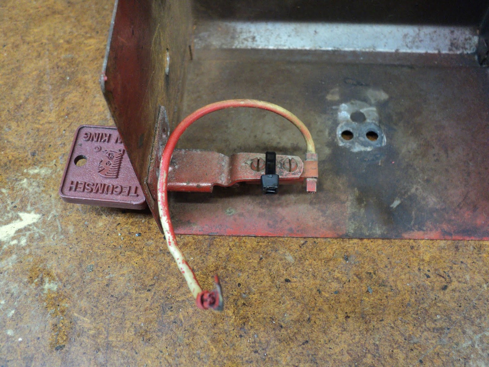
Kill Switch Wire
The kill switch lead has an in-line bullet connector for quick disconnection.
- - -
Exhaust Pipe/Muffler
At the engine -- two M6 x 16mm hex socket head cap screws with split lockwashers, 5mm hex recess. Mind the gasket.
At the rear (see the rear fender photo above) -- one M6 x 16mm hex socket head cap screw, 5mm hex recess, with a flat washer and a Nyloc hex nut, 10mm A/F.
- - -
Engine
Up top -- one M6 x 16mm hex socket head cap screw, 5mm hex recess, with a flat washer and a Nyloc hex nut, 10mm A/F. (The nut goes outboard.)
Underneath the engine platform -- four M6 x 16mm hex socket head cap screws, 5mm hex recess, with split lockwashers and flat washers.
Slip the chain off the engine's sprocket, and the engine can come out the right side of the frame with the throttle cable still connected. The throttle cable terminates at the engine in a cap with a 14mm hex on it. Unscrewing that cap releases what appears to be a throttle plunger, like so.

That's an arrangement that I've certainly never seen before. The design doesn't lend itself to bench-testing the engine.
And here's the engine up on the bench.

There's absolutely nothing on the engine by way of ID.
- - -
Carburetor Removal -- MONDAY, APRIL 29, 2019
Here's an underside view of the air cleaner and its clamp.

The hex on the clamp's worm is 7mm A/F. With the clamp off, I can see that the air cleaner is meant to screw onto a flange.

The female thread is a ruin, though, and the parts don't really mate properly.

Note that the choke is closed with its lever in the 'up' position.
The flange is fastened to the carburetor by two M4 x 10mm truss head screws, No. 2 Phillips recess. With the flange off, you have access to two 4mm hex recess cap screws.

- - -
Utter Defeat -- TUESDAY, APRIL 30, 2019
I dismantled, flushed and blew out the carburetor. With the carb reassembled and back on the engine, it's been no go. I haven't gotten a single 'pop' out of it, and I've tried pretty much everything.
This project is shelved until I find a way past this impasse.
- - -
'Got It To Start And Run -- WEDNESDAY, MAY 1, 2019
The engine has always exhibited what felt like very high compression -- it was difficult to get a long, quick pull on the starter cord. It dawned on me that that characteristic was abnormal, and was interfering with generating spark. (Although recoil starter cranks are short in duration, they're pretty fast. It takes something like 200 rpm to generate spark.)
I had nothing to lose, so I removed the one-piece cylinder to inspect the bore, and the piston and its rings. Nothing looked amiss, but when I went to get the piston back into its bore, the upper one of two piston rings snapped in two places. Here's a view of what's left of the piston ring.

I reassembled the engine with that piston ring omitted, and it started easily and readily. It idles, and accelerates with no load.
So there we are with a bizarre engine failure. The piston ring that broke must have been embrittled and stiff, and it was binding in the cylinder's bore. That's why the engine was so difficult and slow to crank, and so would not start.
- - -
Carrying On -- THURSDAY, MAY 2, 2019
So now I have a working, albeit lame, engine. I'll keep on keeping on. Perhaps a good engine will surface.
- - -
Right Side Foot Peg
It's upside down, its proper M5 fastening is missing; it's been pinned in place with a 1/8" x 1" roll pin.

I don't have a long enough M5 hex socket head cap screw for that, but I do have a suitable 10-32 screw.
I fabricated a 10-32 dowel-nut from 8mm diameter mild steel rod, and reinstalled the foot peg the right way around.

I retained the roll pin. That should work fine.
I don't like to mix inch and metric fasteners on a machine where it was meant to be all one or the other, but the cost and difficulty of always procuring just the right item are horrendous. At least I've done a neat job of it here.
- - -
Centrifugal Clutch
Four M6 x 20mm hex socket head cap screws (5mm hex recess) with split lockwashers fasten the clutch's output end to the engine.

And with that removed, the clutch's innards look fine.

Nothing there needs attention. I'll just button that back up and move on to the roller chain.
- - -
Roller Chain Drive
Here's the engine back in place with the chain installed.

That's a size of chain that I've never encountered before -- it's 1/4" pitch. The 'rollers' appear to be 1/8" long by 1/8" diameter. From what I can find of roller chain specs, that's a No. 25 chain.
The centrifugal clutch's output sprocket is 6 tooth. The rear wheel sprocket is 68 tooth, for a final drive ration of 1: 11 1/3. The chain has 142 links.
The chain was seriously rusty. A soak in solvent and an application of roller chain lube have got it to within reason, but there are still some seizure kinks to be worked out. There's plenty of chain tension adjustment latitude still available at the rear axle.
- - -
A Replacement Engine -- SUNDAY, MAY 12, 2019
My son came up with an engine.

I checked and it has spark, though it has no spark plug connector. Needless to say, that'll have to be rectified.
So, the original, lame engine can come out, and I can install and test this one.
- - -
A Shop-Made Spark Plug Connector -- MONDAY, MAY 13, 2019
The engine's ZBM6A spark plug has a screw-on M4 terminal nut, so I figured I could adapt a ring-terminal-style solder lug as a connector. Here's a view of what I came up with.

Perched on the cowl in the above photo is one of the solder lugs I used. Some electrical tape and shrink tubing made for a nicely strain-relieved termination. And by the way, here's a brief video that explains the various configurations of spark plug terminal.
- - -
An Engine Swap Failure
Right off the bat, I encountered a few snags:
- The throttle cable's threaded connection point at the carburetor was smaller than that on the original engine's carburetor. I had to swap carburetors in order to have a throttle cable connection. The carburetor gasket on the replacement engine didn't survive carburetor removal, so now I'm short a gasket -- I'll have to fabricate one eventually.
- The replacement engine's mounting screw locations weren't exactly the same as those on the original engine. Chain tension had to be slackened off a bit for the replacement engine to go in place.
- The two mounting screw locations at the clutch end of the replacement engine were shallower than those on the original engine, I had to add flat washers to the screws there so the screws wouldn't bottom out.
- The replacement engine's top mounting bracket is configured differently from the one on the original engine. I just left that unfastened.
So, on the face of it, it appears that the replacement engine may have a bad piston ring in it, just like the original engine had.
I took out the replacement engine, and put everything back like it had been. I'm back to having a working, but lame, engine.
- - -
Rear Wheel And Brake -- SUNDAY, MAY 19, 2019
I'd like to examine the rear wheel bearings, and dismantle and clean up the rear brake. 'Hope I'm not opening up a can of worms here.

Rear Axle And Wheel
There's an M10 hex nut at either end of the axle, 17mm A/F. The axle slips out, and two 15mm long sleeves fall away. (This is going to be some fun to get back together.) The wheel position (chain tension) adjusters are free to come away.
The wheel bearings are No. 6000Z -- 10mm bore x 26mm O.D. x 8mm wide. They don't strike me as particularly robust for the load they have to bear. There are no ID markings on the three-spoke wheel rim.
The tires are embossed, "XIANG LONG 110/50-6.5 TUBELESS FOR RACING PURPOSES ONLY NOT FOR HIGHWAY USE MAX PRESSURE 2.5 atm". That's something I've never seen before -- tire pressure stated in atmospheres. One atmosphere = 14.6959 psi, so 2.5 atmospheres = 36.73975 psi; call it 35 psi.
Brake Removal
- Cable end and return spring.
- Front stay fastener.
- Rear stay fastener.
- Lower stay fastener.

And that's as far as I'll go. There's no pressing reason for me to dismantle the actual brake mechanism -- doing so might invite trouble. So, I'll put it all back together.
- - -
New Piston And Rings
After that go-round with the stiffened piston ring that broke and got deleted, my son got a replacement piston and rings from Ebay. Piston diameter is 44mm. The kit includes a wrist pin, wrist pin bearing and two retaining clips.

- - -
The new piston and rings are in. Compression is again quite high, but it's crankable, barely. I got it started, and it has run for a while without seizing up, so maybe I got it right.
- - -
'Beginning To Look Like Scrap Metal -- MONDAY, MAY 20, 2019
Today, it won't start at all, no how. Compression is so high that I can't get a decent long quick pull on the starter cord. I'm baffled.
- - -
'Got It To Start
I took the recoil starter off and applied a nut driver -- powered by a portable drill -- to the flywheel screw's hex head (10mm A/F). That got the engine to start. So I do still have an engine that can start and run. It's just that it has so much compression, I can't operate the recoil starter to good effect.
Recoil Starter Failed
The plastic recoil starter packed it in. The hooked outer end of the torsion spring straightened out and left its retainer. There's no fixing it. I salvaged the cord and handle and junked the rest of it, except for a coil spring that may be useful some day. I installed the starter from my spare engine.
Back To Where I Was
Since the engine with a new piston and rings is unstartable, I decided to go back to the old piston with one ring. With that done, compression is within reason and I can start the engine.
'New' Recoil Starter Cord Failed

The cord's jacket kind of unravelled. I replaced the cord with the salvaged cord from the old starter.
- - -
So, I'm back to a working engine with only one piston ring. If nothing else, this motorbike is a bottomless make-work project.
- - -
Front Fork Time -- WEDNESDAY, MAY 22, 2019
I'd rather not have to do it, but the front fork and handlebars look so bad that they just have to be refinished.

Let the dismantling begin.
Twist-Grip Throttle Control Handle
Loosen off two 4mm hex recess screws, and the handle can be twisted off. The handlebar underneath has been wrapped with tape.

I guess the handle's inside diameter was a little oversize for the handlebar, so that's how the factory 'fixed' the problem. Handlebar length for the throttle control handle beyond the brake lever clamp is 4 23/32".
Front Brake Bracket
Two M6 x 35mm hex socket head screws, 5mm hex recess, with Nyloc hex nuts, 10mm A/F.

Front Brake Lever
Loosen off one No. 2 Phillips recess clamp screw. I had to peel off the tape pn the handlebar to get the brake lever to come off easily.
Left Side Handlebar Grip
It has to be thoroughly warmed with a heat gun to soften it so it can be coaxed off.
Rear Brake Lever
Loosen off one No. 2 Phillips recess clamp screw.
Front Wheel
At the left (brake) side, there's a 17mm A/F Nyloc hex nut and a flat washer. At the right side there's just a Nyloc hex nut. The 10mm diameter axle can be slipped out once either of the two nuts is off.
There are two sleeves between the wheel and the fork. At the right side, the sleeve is 5.5mm long. At the left side, the sleeve is 8.25mm long.
Marking 'L' And 'R'
Now is a good time to mark the fork tubes and handlebars 'L' and 'R' with an engraving tool.
Fork Tube Top End Caps
They're chromed plastic caps that just pry out easily. Note the position of the tops of the fork tubes, just below flush with the tops of the stays.

Kill Switch
Loosen off one No. 1 Phillips from underneath. Disconnect the switch at its bullet connector.
Handlebars And Fork Tubes
Loosen off the various clamps with 4mm and 5mm hex keys. Things are balky from rust, but the pieces do come apart.
- - -
Done And All Back Together -- SUNDAY, MAY 26, 2019


I took it for a little spin, and the left side foot peg broke.

The steel foot peg stud only extends part way through the peg, so the peg snapped off right at the end of the stud. The more I see of this motorbike, the less favourably impressed I am by its engineering and construction.
I had a salvaged M12 x 84mm bolt, so I bored 12mm diameter through the entire length of the peg. That gave me a fully reinforced foot peg.


I'll put it up on Kijiji and see if I can unload the thing.
- - -
Update -- FRIDAY, OCTOBER 11, 2019
I never did manage to sell the thing. I've given up and withdrawn the Kijiji ad.
I tried starting it again a couple of days ago, and the starter's recoil spring broke, so there's an end to the project.
From what I've seen of pocket motorbikes, the things are junk. I'm unlikely to ever see another one, but in the event that I do, I'll be inclined to stay well clear of it.
- - -
To be continued.
# # #
# # #