[Last updated: Thursday, April 25, 2019.]

The "5/23" indicates 5 hp/23 inch swath. Model number is C950-52672. Serial number is 370984 68. It was made in Canada, so it must be a real old-timer.
The engine starts and runs reasonably well, and the transmission works. The machine won't freewheel satisfactorily at all; it sort-of freewheels if you drag it from the front.
There's a foot pedal affair at the rear of the carriage that mystifies me. With the foot pedal in its up position, the whole frame of the machine can be tipped up in front from the rear of the carriage. Pressing the foot pedal down locks the frame to the carriage. I think that feature may have something to do with freewheeling.
Googling for a user's manual has turned up nothing; the model seems to scarcely exist online, so I'm really on my own here.
Like any old piece of equipment, the machine is due for some TLC throughout, but the absence of easy freewheeling is especially troubling. I'll concentrate on getting that sorted out first, so I'll get the engine off, and the auger housing separated from the frame. That should leave me with a manageable unit that I can unravel the mysteries of. I really must resolve the freewheeling issue to make the machine nicely useable.
- - -
Discharge Direction Crank Removal -- TUESDAY, APRIL 16, 2019
At the front end, a cotter pin and washer.

And up at the handlebar, a 3/8"-16 eyebolt's nut and washers. (9/16" wrenches needed.)

Discharge Chute Removal
Three 5/16" x 3/4" carriage bolts with 5/16" SAE flat washers, split lockwashers and 1/2" A/F hex nuts.

V-Belt Drives Cover Removal
Two 1/4"-20 x 1/2" hex washerhead screws, 3/8" A/F, with 1/4" SAE flat washers. With the cover off, the V-belt drives are revealed.

The 1/2" wide belt at the left in the above photo is auger drive. The 3/8" wide belt to the right is locomotion drive.
The auger drive belt's tension idler is operated by the right side lever on the handlebar. The locomotion drive belt's tension idler is always operational; a spring keeps it in the belt-tensioned position.
Now is a good time to carefully check pulley alignment. If anything is off, determine what measure(s) will have to be taken to correct the problem. If all is correct, note/sketch how idlers are assembled; check for asymmetrical idler hubs, and the presence of washers. At the auger drive pulley, note the position of the fastening in the tension arm's adjustment slot.
- - -
Engine Removal
Four 5/16"-18 x 1 1/4" hex head screws, 1/2" A/F, with split lockwashers. Tip the engine up from the rear to slacken off the V-belts, and slip the V-belts off their engine pulleys. With the engine away, the locomotion V-belt is free to come out. The belt measures 31 3/4" outer circumference (O.C.).
- - -
Unit Upended

With the engine off, it's fairly easy to tip the machine up onto the face of the auger housing.
I've decided to leave the auger housing attached to the transmission frame for now. It looks like it'll be a lot easier to deal with the Trac-Drive's troubles with the machine standing up like this.
- - -
An Obvious Flaw
The left side pivot screw for the foot pedal is missing.

Whether that has any bearing on my freewheeling problem, I don't know, but I doubt it. In any event, that flaw must be corrected. It looks to me like a special shoulder screw was there originally. I'll have to fabricate something for a replacement.
- - -
Bottom Cover Off

Nothing looks amiss inside the transmission. It looks just about like any other snowblower transmission. The Trac-Drive is incredibly stiff, though. I suspect that much of the engine's power has been eaten up just to make the Trac-Drive operate.
I'll get after that missing foot pedal pivot. Once I've got that corrected, I can pursue dismantling the Trac-Drive.
- - -
Missing Pivot Screw Re-Created -- WEDNESDAY, APRIL 17, 2019

At the left in the above photo is my new pivot screw, made from an ordinary 5/16"-18 hex head screw and hexnut. The head is undersize at 1/2" A/F, but it's still adequate for the installation. (The hex head on the original screw at the right is 5/8" A/F.)
The shoulder bushing is 7/16" diameter x 17/64" long, exactly matching the shoulder dimensions of the original. The screw's head has been turned down to a height of 9/64", matching the height of the original screw's head. I've attached the shoulder bushing with red threadlocker.
- - -
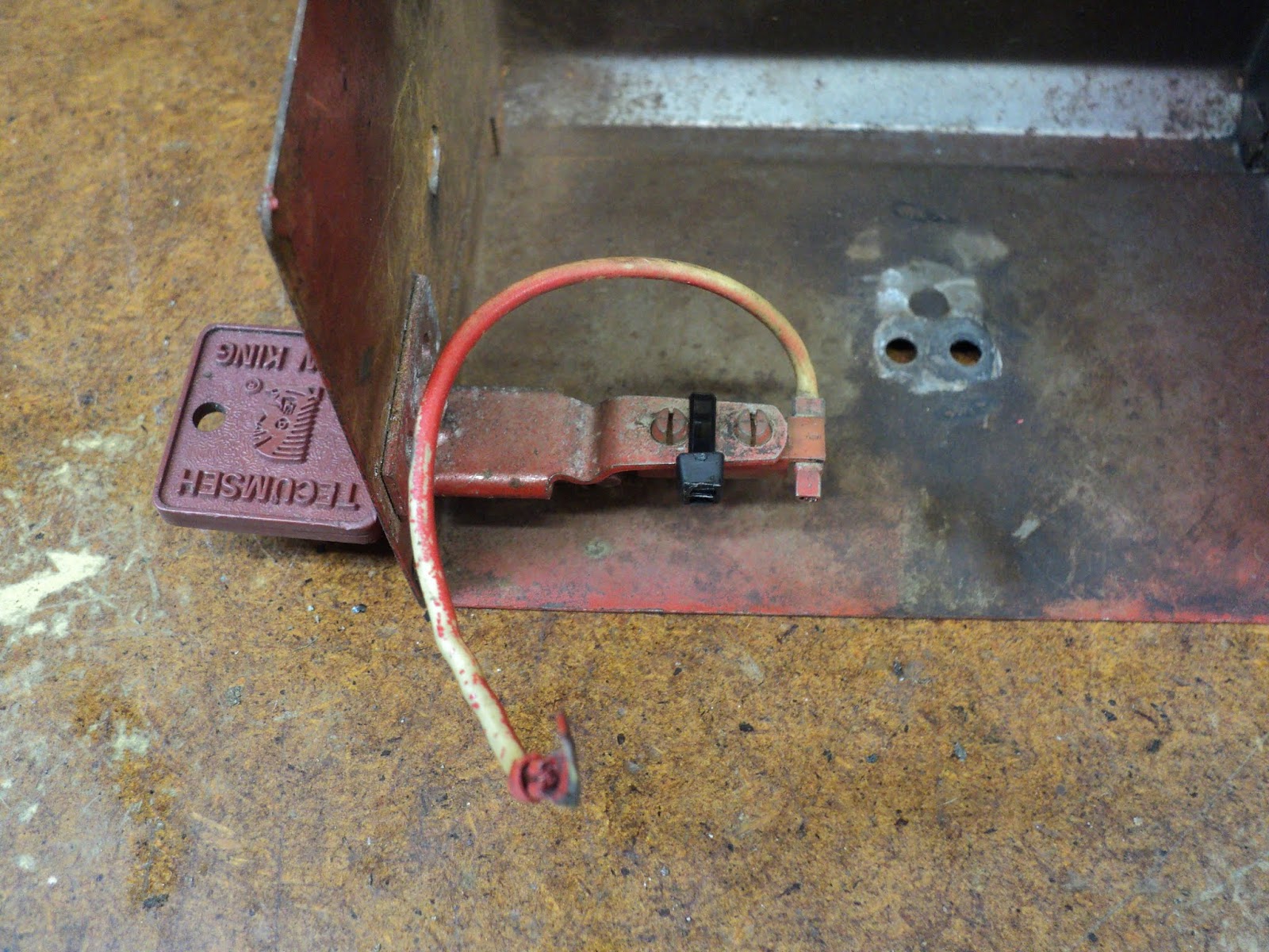
Pivot Screw Installed

Note the Nyloc nut. Originally, there would have been an ordinary hex nut and a split lockwasher. That's where the designer went wrong.
The forcefully spring-loaded foot pedal crank exerts considerable torque on the shoulder of the pivot screw whenever the foot pedal is operated -- enough that a split lockwasher wasn't up to the task of keeping a nut from loosening. Once loosened enough, the nut 'walked' away, and the nut, lockwasher and original pivot screw went missing. A Nyloc nut should stay put, even with a slight bit of loosening. A prevailing torque nut might be better yet, but I don't have any of those.
Note also the wire loop. That's there to restrain the end of the spring from creeping leftward. A pushnut was there originally to serve that function, but that's been lost as well.
- - -
Trac-Drive Outer Plate Removal
- Two 1/4"-20 x 1/2" hex washerhead screws, 3/8" A/F.
- At the front, a 5/16"-24 x 1/2" hex head screw, 1/2" A/F with a flat washer and a ring washer.
- At the rear, a 5/16"-24 x 1/2" hex head screw, 1/2" A/F with a flat washer and a track-tensioning eccentric.

And now I can see why this snowblower won't freewheel -- the rear idler wheel is seized on its axle. The whole Trac-Drive assembly is going to have to come apart, and that's going to be challenging.
- - -
'Got The Rear Idler Wheel Out

That wasn't too difficult after all. I undid the axle screw on the inboard side, and that permitted the wheel enough freedom that it could be removed from the track. The track is now free to come off as well.
What we have here is sketchy design. The plastic wheels turn on steel axles with no provision whatsoever for lubrication. When new, the low-friction plastic-hub/steel-axle interface worked nicely. With age the steel axles oxidize and the hubs bind. The outcome is a snowblower that won't freewheel.
Anyway, I should now be able to hammer the axle out of the idler wheel, and get that all freed up. I'll give the front cog wheel and the chain drive plenty of roller chain lubricant, then repeat on the other side of the machine.
- - -
Axle On Its Way Out

Hammering didn't budge it. I got it that far with the hydraulic shop press. I should be able to knock it the rest of the way out with a hammer and a punch.
The axle is very badly corroded; it's little wonder that the snowblower wouldn't freewheel. The idler wheel on the other side is not as bad, but it's stiff.
- - -
Left Side Trac-Drive Back Together
And it's freewheeling nicely. As it turned out, the front axle was in pretty bad condition as well. I wire brushed both axles on a wire wheel machine, and reinstalled them with Molyslip grease for a lubricant. That should keep things in good order for a long time. So it's on to the right side Trac-Drive, which appears to be in less bad a condition.
- - -
Both Trac-Drives Reassembled And Installed -- THURSDAY, APRIL 18, 2019
The machine now freewheels, and can be pushed and pulled about, albeit with effort. Tracks inherently offer more more rolling resistance than do wheels, and this snowblower will never move as easily as a wheeled snowblower will. That's the price to be paid for the superior traction provided by the Trac-Drive.
Scraper Bar And Skids

All fasteners are 5/16" x 3/4" carriage bolts with 5/16" SAE flat washers, split lockwashers and 1/2" A/F hex nuts.
The scraper bar seemed too low for the auger height that I wanted, so I reversed it to get it up higher. I set the skids for lowest possible auger height. I now have scraper bar clearance of about 1/8", with auger clearance of about 1/4". That should be ok for smooth pavement. A gravel driveway would call for greater clearances.
Separating The Auger Housing From The Frame
(The green twist-tie in the photo below is there to keep the locomotion V-belt tension idler's spring taut. The bottom end of that spring tends to leave its anchoring notch in the frame if the spring is allowed to go slack.)
The auger housing is fastened to the frame by four 5/16"-18 x 1/2" hex washerhead screws, 1/2" A/F. The two lower screws need to be loosened off, not removed. The screws are very awkward to get at. You may want to stand the machine up on the face of the auger housing to gain access to them. Then.,with the machine level as for normal use, remove the two upper screws. Tip the frame up and the two lower screws will act as hinge pins. That gets you to here.

The auger drive V-belt can be removed, and the condition of the impeller bearing can be checked. Auger drive V-belt outer circumference (O.C.) is 30 1/4". The impeller bearing on this machine feels ok. I suspect that the bearing has been replaced at one time because the set screws in the auger drive pulley are not the original 5/16"-18 square heads; they're 3/8"-16 hex heads.
When re-mating the assemblies, clamp the auger clutch lever to the handlebar with a suitable spring clamp. That'll keep the auger drive brake shoe out of the way of the auger drive pulley.
Locomotion And Auger Drive V-Belt Tension Idler Pulleys
The two idler pulleys are identical. The fastenings are 3/8"-16; two 9/16" wrenches are needed to remove them. Note the orientation of the pulleys' asymmetrical hubs, and the placement of flat washers. At the auger drive pulley, note the position of the fastening in the tension arm's adjustment slot. The thin hex nuts are prevailing torque types.
The pulleys' bearings are integral with the sheaves. The bearings have seals, but roller chain lubricant can be applied so it will wick into older bearings to extend their life.
- - -
Engine -- FRIDAY, APRIL 19, 2019
It's a 5 hp Tecumseh Snow King. There's supposed to be a Sears engine model number on the cowl somewhere, but I can find no trace of one. There are several things I want to attend to:
- Carburetor dismantled and cleaned.
- Fuel delivery tubing redone.
- Cowl and flywheel off -- ignition system inspected.
- Choke knob pulled off.
- Keyed kill switch wire disconnected -- one No. 8 x 3/8" pan head threading screw in a bracket below the carburetor cover, No. 2 Phillips recess.
- At the top, right by the muffler -- one 10-24 x 3/8" hex washerhead screw with external tooth lockwasher, 5/16" A/F.
- At the left side -- two 8-32 x 5/16" pan head screws with captive external tooth lockwashers, No. 2 Phillips recess. (One of the two screws is missing on this engine.)

A ty-wrap may fix that.
The governor link has a peculiar kink in it.

That arrangement looks very sketchy. The throttle can't open fully; the governed speed controller's speed adjustment screw is at maximum. The governor linkage has obviously been tinkered with, no doubt to ill effect. To be attended to in due course.
- - -
Spark Plug
It's a Champion RJ19LM. Gap is 0.030". The spark plug looks fine -- nearly new.
- - -
Cowl Removal -- Governed Speed Controller
[Note -- SUNDAY, APRIL 21, 2019: The following bit about the governed speed controller is in error. It turned out that the governed speed controller is not attached to the cowl.]
This looks dreadful.

The governed speed controller appears to be riveted to the cowl. There's no provision for disconnecting the kill switch, short of dismounting the kill switch contact itself, which I'd rather not have to do.
I think I'll install a quick-disconnect right now, and have that aspect of the machine corrected for good.
- - -
And here we are with a 3/16" in-line spade terminal arrangement.

So that's taken care of. The kill switch can be disconnected, and the governor spring unhooked to begin the process of removing the cowl.
At the kill switch terminal bracket, there's a 1/4"-28 x 7/16" hex head screw with captive external tooth lockwasher.
At the carburetor, disconnect the primer tube from its nipple.
Cowl Removal -- Electric Starter Drive Entry Point Cover
This engine can accept an electric starter motor. When such is not installed, there's a cover for the area where the electric starter's drive would enter the cowl.

High up is a No. 8 x 3/8" pan head threading screw, No. 2 Phillips recess. That screw is awkward to get at; an offset screwdriver is called for. Lower down there's a 1/4"-20 x 1/2" hex head screw with captive external tooth lockwasher and 1/4" SAE flat washer, 7/16" A/F. That screw is also a cowl fastener.
Cowl Removal -- Upper Fasteners
This looks peculiar to me.

Surely none of those three screws associated with the top of the cowl can be cylinder head screws. Let's see. The screws' hexes are 1/2" A/F.
- - -
I got the centre screw out, and it appears to be a cylinder head screw. The remaining two screws are very tight, and I can't get enough purchase on the engine with the engine off the frame on a work surface. I'll have to reinstall the engine on the snowblower's frame.
- - -
Two Out Of Three Out
'Got the engine reinstalled on the frame and the leftmost screw out without breaking it. Here goes for the remaining screw.
- - -
And that's three for three. The screws are hex washerhead 5/16"-18 x 2", 1/2" A/F. They're three of the cylinder head screws.That strikes me as lunacy -- to have the cowl fastened by cylinder head screws.
Anyway, I've got the cowl off, and the ignition system appears to be solid state, so I don't have to worry about breaker points maintenance.
And by the way, I was wrong about the governed speed controller being riveted to the cowl; it's riveted to the same flange that the cowl attaches to -- it's not attached to the cowl at all. So my earlier exercise in installing a quick-disconnect was needless, really.
Here's a view of the flywheel and ignition coil.

There's no pressing reason for me to take the flywheel off, now that I know there are no breaker points to be examined, so I'll button that back up and attend to other things.
- - -
Carburetor
Dismantling the carburetor revealed nothing amiss. I flushed it with solvent and blew it out/through with compressed air. The model number embossed on the carburetor's body is "1085 H6H".
Governor Link
I straightened the bent governor link, and moved its lever-end connection over to where the throttle butterfly is now afforded full travel.

Fuel Delivery Tubing
'Tidied it up. Deleted the oversize paper element filter and replaced it with a smaller mesh filter that I had on hand.

The tubing is all 1/4" I.D.
Keyed Kill Switch
It's back in place with a ty-wrap securing it.
Discharge Chute
Reassembled with proper carriage bolt fasteners, instead of the truss head screws that it had in it. Lock knob relocated to left side. Lubricated with roller chain lubricant.

The machine is ready to go outside, where I can run it up properly and see about governor and carburetor adjustment. An oil change is in order as well.
- - -
Oil Change -- MONDAY, APRIL 22, 2019
In my area, winter temperatures seldom go below zero Fahrenheit (about -18 Celsius), so 5W30 oil is fine. For temperatures consistently below zero Fahrenheit, Sears recommends synthetic 0W30.
The hexagonal oil drain cap takes a 5/8" wrench. You may need to grip the oil drain tube with Vise-Grips to prevent the tube from unscrewing instead of the cap.
Nowhere could I find an oil capacity figure. My engine took 600ml (about 20 fl. oz.) to fill.
- - -
Shear Pins -- THURSDAY, APRIL 25, 2019
As is so often the case on old snowblowers, the shear pins on this machine were a kluge. Here's a view of one of the 'shear pins'.

That's an SAE Grade 5, 1/4"-20 screw employed as a shear pin. SAE Grade 5 is pretty tough -- not something you'd want to rely on to shear when it's supposed to. I got the proper items from the small engines place in Pickering.

1/4"-20 x 1 3/4" hex head screws with collars and Nyloc hex nuts. The collars go under the screws' heads, and fit into oversize holes in the augers' axle sleeves.

The finished installation looks like this.

The screws' heads are marked "307A". 307A indicates a screw hardness nearly equivalent to SAE Grade 2 -- a relatively soft, low carbon steel. There's a technical note on 307A here.
- - -
Why The Collars And The Oversize Holes? -- THURSDAY, APRIL 25, 2019
The only reason I can think of is so that no amount of tightening will squeeze the auger axle sleeves down onto the auger axle shafts; i.e. 'clamp' the augers to their axles.
- - -
To be continued.
# # #
# # #
Where does the other end of the keyed kill switch wire go?
ReplyDeleteTo the ignition coil, as I recall.
DeleteI received a snow blower almost exactly like this one. I found that the ignition wire was not attached to anything on the "hook" end. I'm trying to find out where I need to attach this and if I need to buy a screw and locking washer for it. I'm kind of a visual person and really just starting out with fixing things myself, so any other help would be much appreciated.
DeleteIn short, I have no idea where or what the ignition coil is/ looks like.
Delete'Sorry. My snowblower is long gone, so I can't look into it for you. Check with a local small engines repair outfit.
DeleteRegards,
Tom
Thanks for your responses. I might have to do just that.
DeleteWere you able to find where the engine model number is located ? I’ve looked all over mine without luck.
ReplyDelete