[Last updated Thursday, April 25, 2019.]
Well, there appears to be a snowblower in my workshop.

It's huge. The 11.0/31 model number presumably stands for '11 horsepower/31 inch swath' -- we're talkin' BIG snowblower here. It's a Sears Canada Inc. Model No. C950-52930-0; Serial No. 742112669CJ00122; Code 9266; Made in U.S.A.
The Sears engine model number is 143.01103. (Tecumseh model number HMSK110, possibly.) Engine Family XTPXS.3582BF. Displacement 358. D.O.M. 9217 R.
The machine is allegedly a 'won't start' case. We'll see what's up with that in due course.
- - -
Big Trouble -- MONDAY, MARCH 18, 2019
There's a crank arm missing for auger drive engagement, and a roller chain is off its sprocket inside the transmission. Hmmm. What I may have here is a large piece of scrap metal. We'll see.
A rudimentary plan is in order. Here goes:
- Headlight off.
- Discharge chute off.
- V-belt drives cover off.
- V-belts off.
- Engine attended to.
- - -
Headlight Removal
- Power Lead -- one quick-disconnect.
- Ground Return Lead Ring Terminal-- one 5/16"-24 x 5/8" hex head screw, 7/16" A/F with T40 Torx recess.
- Mast -- two 1/4"-20 Nyloc hex nuts, 7/16" A/F.

I'm sure that can be improved on.
The headlight's light bulb is open. It's a No. 1156. I have a spare.
- - -
Headlight Mast Repaired And Installed -- MONDAY, MARCH 25, 2019
I retained the two straps, but attached them with 6-32 machine screws, No. 6 SAE flat washers, Keps nuts and CA adhesive.

I added a third strap on the inboard side of the mast. (It's not visible in the above photo.) That's a solid repair that will be trouble free.
I've also replaced the bad light bulb. Now I just need to start the engine to see if the light works.
- - -
It Works! -- TUESDAY, MARCH 26, 2019
I didn't start the engine, I just cranked it with the electric starter, and that made the light bulb glow. So the snowthrower has its headlight back.
- - -
Discharge Chute Removal
I mean to remove the whole thing with its discharge height control cable and its discharge direction crank.
The discharge height control cable needs to be disconnected at the control lever.

The 'Z' fitting won't come out without loosening off the lever somewhat. 9/16" wrenches are called for. With the 'Z' fitting free of the lever, the cable's sleeve end can be freed from its bracket.
The discharge chute is attached by three obvious bolts and nuts. A 1/2" wrench is needed.
The discharge direction crank attaches to its universal joint with a clevis pin and a cotter pin. It attaches to the handlebar with a 3/8"-16 eye-bolt and a Nyloc nut, 9/16" A/F.
- - -
Discharge Chute Rotation Worm Gear -- SATURDAY, APRIL 6, 2019
The worm gear for chute rotation has a bad spot that makes for lumpy chute rotation. A replacement worm gear is P/N 585196.
With the discharge chute off the machine, you have access to the two 1/4"-20 screws and nuts (7/16" A/F) that hold the worm gear's mounting bracket in place.

A 7/16" nut driver is helpful for reaching up from underneath to hold the two screw heads from turning, while you undo the nuts. Here's the worm gear with its mounting bracket off the auger housing.

And here's a view of the old worm gear where you can see the defect.

With the new worm gear installed, discharge chute rotation is now smooth.
- - -
V-Belt Drives Cover
Here they are.

The 1/2" wide belt to the left is auger drive. The smaller (3/8" wide) belt to the right is locomotion drive. It's easy enough to untension the belts and slip them off their engine pulleys. To remove the auger drive belt entirely, the auger housing must be loosened off. The locomotion drive belt can be readily removed once the auger drive belt is off its engine pulley and out of the way. Locomotion drive belt outer circumference (O.C.) is 33 1/4".
And with all that done, I can get on with getting the engine running.
Spark Plug
It's a Champion RJ19LM, a resistance-type spark plug, as the engine parts list calls for. It's in pretty good condition and correctly gapped.

A test has shown that I have spark. What I may not have is a reliable 'kill' function. The kill key-switch is missing, and the speed control lever's kill function seems to be flaky.
- - -
Carburetor Cover And Carburetor
Here's a view of the carburetor cover.

There's a 10-32 fastening screw missing from the cover's upper right lip. Two remaining 10-32 No. 2 Phillips recess screws are holding the cover on.
Here we are with the cover removed.

Note that the primer tube is split right at the nipple. I fixed that and tried priming the carburetor. The primer bulb works; the fuel that emerges looks more like dish detergent than gasoline. I tried starting the engine, and it's no go. I'll proceed to do the following:
- Drain and remove the fuel tank.
- Rinse the fuel tank with methyl hydrate and set it aside by the furnace to dry out thoroughly.
- Remove, dismantle and clean the carburetor.
- Rinse the fuel supply tube and dry it out with compressed air.
- Button everything back up and try the engine with fresh fuel.
- - -
Fuel Tank Drying Out -- TUESDAY, MARCH 19,2019
I perched the fuel tank on the furnace like so.

Furnace rooms are very dry places; that worked well. An overnight spell on the furnace got the tank completely dried out.
- - -
The Carburetor Opened Up

Oh, yuck! There was water in the float bowl. I'll clean and rinse the carburetor, and see if I can get away without installing a complete carb kit.
- - -
Carburetor Ready -- TUESDAY, MARCH 19, 2019
Here's the cleaned up carburetor.

Note the following:
- There are no mixture adjustments. Both the idle and main jets are fixed jets.
- Float level adjustment is not as critical as it's made out to be in the 'literature'. Get the float level with the body of the carburetor when the needle valve is closed, and you're plenty close enough.
- - -
Starter Motor
Since the fuel tank is still off, this would be a good time to remove and inspect the starter motor and its drive. Proceed as follows.
- Switch Box: two 6-32 x 2 1/2" hex head screws, 1/4" A/F with No. 2 Phillips recess.
- Fuel Tank Ledge Bracket: one 1/4"-20 x 5/8" hex head screw, 7/16" A/F with captive washer.
- Starter Motor --
- Two Upper Screws: 1/4"-20 x 1/2" hex washerhead shoulder screw, 3/8" A/F. Note that these two shoulder screws serve to precisely position the starter motor.
- Two Lower Screws: 1/4"-20 x 1/2" hex washerhead screw with captive external tooth lockwasher, 3/8" A/F with T30 Torx recess.
- - -
It Starts
'Could only run it for a few seconds inside the workshop. So it's on to getting at the transmission, where the serious trouble resides.
- - -
Engine Removal
- Four 5/16"-18 x 1 1/4" hex washerhead screws with split lockwashers, 3/8" A/F.
I got just shy of 50psi. It improved slightly with oil squirted in. Tecumseh calls for 80psi for a new engine; no less than 60psi for a used engine, so we have a well worn engine here, but I think the compression is still within reason. I took the engine outside to try it out. It runs more-or-less satisfactorily.
- - -
Auger Housing Removal
Note the following:
- The auger housing is attached to the transmission frame by six 5/16"-18 x 1/2" nominal length hex washerhead thread rolling screws, 1/2" A/F. The two upper screws at the right side are also the fasteners for the headlight mast bracket.
- Have the handlebar supported so it can't drop. Loosen off the two lower screws; remove the four upper screws. The two lower screws will act as hinge pins to help you safely separate the assemblies.
- Let down the handlebar.
- Take away the auger drive V-belt.
- Fully separate the auger housing from the transmission frame.

The fastener complement that I cited a bit earlier for the auger housing is correct, but the fastener complement on this machine wasn't quite; it's pictured above. One screw is missing, and one screw is not quite right.
Four of the five screws pictured are 5/16"-18, as they're supposed to be. The 'odd man out' is metric -- it's an M8 x 1.25 screw. M8 is very close to 5/16", but it's not a fit. The M8 screw had been forced into a 5/16" threaded hole to replace a missing screw. The things that tinkers do to machinery.
- - -
Transmission Fault Figured Out -- WEDNESDAY, MARCH 20, 2019
It was a user error that fouled up the transmission. I'll try to explain.
Snowblowers of this class generally have a feature that permits the left side wheel to freewheel (one wheel drive, in other words). The freewheeling feature enhances machine maneuverability at the expense of traction. The feature is invoked by repositioning a wheel-to-axle locking pin. (Craftsman calls the pin a 'Klik pin'.) Here's the entry from the Owner's Manual that explains the feature.
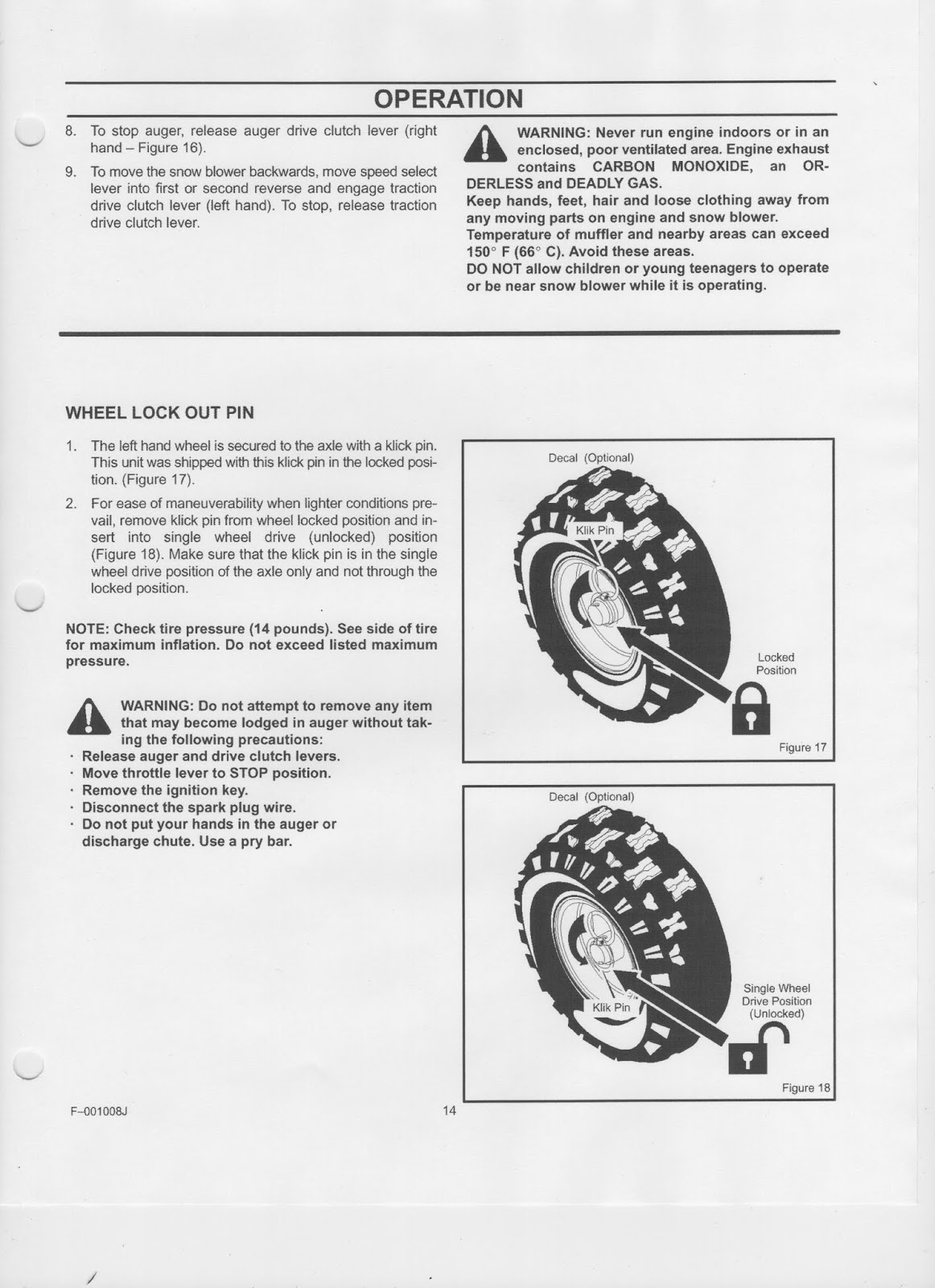
Here's a view of the subject wheel in its locked (two wheel drive) configuration.

Note the relationship of the wheel's hub to the end of the axle; the hub is almost 1/2" inboard from the axle end.
Here's a view of the subject wheel in its unlocked (free wheeling, one wheel drive) configuration.

Note that the wheel is no longer locked to the axle, but the wheel hub's relationship to the axle end is unchanged; the wheel's hub is still about 1/2" inboard of the axle end.
And here's a view of how the Klik pin was installed when I got the machine.

The Klik pin is mis-installed. The wheel's hub is flush with the end of the axle.
That permitted the axle with its roller chain sprocket to shift over rightward inside the transmission. The roller chain jumped off its sprocket, and the shifter fork got tangled in the sprocket rendering the mechanism inoperative.

Craftsman could have precluded such an event had they simply installed a collar on the axle at the inboard side of the right side axle bearing. That would have prevented the axle from shifting over rightward in the event that a user mis-installed the Klik pin.
Anyway, the transmission has to come apart so I can get the shift fork out to straighten it. I may as well install a collar while I'm at it. I happen to have a 3/4" shaft collar on hand.
- - -
Further To Axle Rightward Shift Preclusion
The axle design as documented in the illustrated parts breakdown features a retaining clip that would prevent the axle from shifting over rightward.

The clip is item 678 in the illustration.
The axle in this machine has no clip, nor is there a groove for a clip. Instead, there's a push-nut that's supposed to prevent the axle from shifting rightward.

The only problem with that is that the push-nut fails utterly to do its job. The push-nut doesn't grip the axle firmly enough to prevent the axle from shifting over rightward. Not one of Craftsman's better moments.
- - -
The Bent Shifter Fork

That shifter fork is a welded-on part of a shifter crank. The crank appears to be impossible to remove from the transmission's frame; the welding must have been done with the crank first installed in the frame. I'll have to manage to straighten the bent fork in situ.
- - -
That turned out to be easier than I expected. I got the fork straightened out and re-engaged with its friction wheel assembly. I only had to drop one end of the friction wheel's hexagonal spindle in order to re-engage the fork.

Note the flat spot on the friction wheel's tire. That's unfortunate, but I'll live with it.
- - -
Axle Re-installation
Here's a flat spot filed on the axle to take the setscrew of a restraint collar.

And here's the axle re-installed with a restraint collar and a bronze thrust washer by the right side bearing.

The final drive sprockets line up as they ought to; the transmission is almost back in business. Now I just have to lube the final drive chain, clean the friction drive, install the left side wheel and button up a couple of fasteners.
- - -
And here we are with both wheels back on and everything lubricated. The friction drive surfaces have all been cleaned with lacquer thinner.

The friction wheel's position is at the low forward speed. The wheel moves rightward for the higher forward speeds; leftward past centre for the two reverse speeds.
Next up will be to attend to the auger housing assembly.
- - -
Auger Drive Pulley -- THURSDAY, MARCH 21, 2019
It's an 8 1/2" diameter pulley fastened by a 1/2"-20, 3/4" A/F prevailing torque type hex nut. I took the nut off just for a look-see.

There's a keyway and key, and for certain that pulley is stuck fast to its spindle. So this is a point at which to let discretion be the better part of valour, and leave well enough alone. The rear impeller bearing appears to be ok, so there's no pressing reason for me to try to get the pulley off. Applying a puller will without a doubt distort the pulley. I'll put the washer and nut back on and attend to other things. As the saying goes, "If it ain't broke, don't fix it." If ever that pulley does have to come off, I'll want to have a new pulley on hand to replace it with.
The auger housing is set very high for a gravel driveway. I'll adjust the skids for an auger height suitable for smooth pavement. I'll deal with the 5/16" attachment thread that had an M8 screw rammed into it, and lubricate the auger's end-bearings. With all that done, I can reattach the auger housing to the transmission frame.
- - -
Back Together Less Engine

Getting the two major assemblies lined up and refastened together is a ticklish bit of business, best done with assistance. I managed it alone with the aid of some props to hold things in position.
Auger Housing Height
There's broad adjustment latitude for auger housing height -- about 1 1/2".

Pictured above is the left side skid set for lowest possible auger height. That setting puts the auger's periphery about 1/4" above the pavement. For a gravel driveway, one would want to have the skids set for greater auger height, to avoid picking up and hurling stones.
Scraper Bar
There's a scraper bar across the lower rear of the auger's mouth.

It's fastened by six 5/16" x 3/4" carriage bolts and nuts. The bar is supposed to be adjusted for a 1/8" height above pavement; higher for gravel.
Adjusting the bar means loosening it off, and that may be a chore on an old machine with well rusted carriage bolts. I had quite a time of it, but I managed to get all the bolts and nuts freed. Cleaning up the bolts on my wire wheel machine, and chasing the nuts' threads with a 5/16"-18 tap salvaged the fasteners. I reassembled the fasteners with anti-seize compound.
Adjusting and retightening the bar is awkward. It's best done with assistance -- someone to stand on the handlebar to keep the auger housing up where you can get at the scraper bar's nuts easily, like so.

- - -
A Bottom Cover For The Transmission -- FRIDAY, MARCH 22, 2019
The machine is missing its bottom cover.

That was really bugging me. Any safety consideration aside, I could too easily imagine snow getting kicked up into the friction drive and fouling up the works.
A replacement cover can be had from Sears in the USA, but I'd be looking at about $100.00 CDN to get one. So, I decided to fabricate a cover.
Sheet metal work is not one of my strong suits; it's an art and a science that I'm ill equipped for in terms of both learning and equipment. So, I opted for making a wooden cover. I figure that if I prime and enamel a wooden cover adequately, it will serve and last. Here's a view of what I came up with part way built.

And here it is completed, ready for primer and paint.

It's held together with screws and nails and Gorilla Glue. I managed to get the fastening points well located, so the thing installs without a struggle. (Final installation will be done with the snowblower fully assembled and upright, so it had better go on easily.)
I have some Tremclad grey primer and some Tremclad gloss black enamel on hand -- those will do nicely for a finish
- - -
Mouse Nest Removal -- SATURDAY, MARCH 23, 2019
There's been some home-building activity under the engine's cowl.

That must be removed -- it will interfere with cylinder head cooling. So, the engine's cowl has to come off. While I'm at it, I may as well pull the flywheel and replace the 1/4" I.D. fuel line tube. Removing the cowl involves the following:
- Governed Speed Control removal: Note/sketch the location of the governor link. Two 10-32 hex washerhead screws, 5/16" A/F. Unhook the governor link. Let the unit dangle by its kill switch wire. (Some tinker had replaced the upper screw on this machine with a 10-24 screw.)
- Electric Starter Switch Box: Two 6-32 x 2 1/2" hex head screws, 1/4" A/F with No.2 Phillips recess. Let the unit dangle by its cord.
- Transmission Speed Shifter Rod: Remove its cotter pins and remove the rod.
- Primer Tube: Pull it off the carburetor's nipple.
- Cowl: Two 5/16"-18 x 3/4" hex washerhead screws up top, 1/2" A/F. Lower down there are two 5/16"-24 x 5/8" hex head screws with captive split lockwashers, 7/16" A/F with T40 Torx recesses.

Quite the job. That would pretty much inhibit cylinder head cooling altogether.
Flywheel Removal
Here's what I rigged for removing the 15/16" A/F flywheel hex nut.

That's a Vise-Grip 20R chain clamp on the starter cup, jammed against a length of 2"x3". It's a better way to do it than by jamming a bar in the flywheel's cooling fins -- there's no risk of breaking anything. A deep 15/16" socket is called for.
Here's the puller rigged.

Note that the puller's jaws go under the flywheel's flange, not under the ring gear.
And here we are with the flywheel off.

There are the alternator coils that power the headlight. Three magnets inside the flywheel serve to energize the coils. The thread on the end of the crankshaft is 5/8"-18. Note the path of the fuel line tube that is to be replaced.
I can't get new tubing until Monday, so I'll set aside the tubing replacement job for now and attend to the clutch levers and the missing auger drive engagement crank arm.
- - -
Clutch Levers Slop -- SUNDAY, MARCH 24, 2019

There's a lot of slop in the clutch lever pivots. I think I can get rid of much of it with a couple of bushings made from hard brass tubing.
- - -
Here's a bushing installed at the right side (auger drive) clutch lever pivot point.

That's a 1 1/4" length of 11/32" outside diameter brass tubing. Inside diameter is 5/16", which just fits the pivot pin.
Reassembled, there's an improvement -- some of the slop is gone, but not as much as I'd hoped for. To really get rid of the slop, I'd have to bore out the pivot pin holes to 3/8" diameter and install 3/8" pins in place of the original 5/16" pins. I'm not prepared to go that far just yet, so I'll just bush the left side's locomotion clutch lever pivot as well and leave it at that.
- - -
Auger Drive Engagement Crank Arm
For better or worse, here's what I've come up with.

I fabricated that from a 1/2" NPT floor flange, a 1/2" NPT plug and a six inch length of 1 1/2" steel flat. It'll work.
Adjustment is finicky. The V-belt tension idler pulley wants to be all the way inboard (greatest tension position). The V-belt's length is correct according to the parts list, but it looks to me like a slightly shorter belt should have been specified. The belt tension that I've achieved feels to me like it should be adequate; any more tension would make for fatiguing clutch lever operation.
I'm beginning to suspect that the design of the whole auger drive belt tensioning scheme is marginal at best, slightly flawed at worst.
- - -
Friction Wheel Replacement -- TUESDAY, MARCH 26, 2019
That flat-spotted friction wheel tire was bugging me, so I bought a replacement. Here's the procedure for replacing the friction wheel.
[NOTE: This procedure is fraught with peril. The roller chain from the hexagonal shaft to the intermediate shaft can jump a tooth on its large sprocket once the hexagonal shaft's bearings are loose. Getting things back in place will be trying. Try to keep the roller chain taut throughout the procedure.
- Snowthrower upended onto the front of its auger housing. One will need assistance if the engine is on the machine. With the engine off, one man can easily handle the chore.
- Bottom cover off.
- Friction wheel unbolted from its hub -- three 1/4"-20 x 5/8" hex head screws with Keps nuts, all 7/16" A/F.
- Left and right side friction wheel spindle bearings unfastened -- four 5/16"-18 x 1/2" nominal hex washerhead thread rolling screws, 1/2" A/F.
- Coax the spindle out of position so that the friction wheel can be eased past the right side end of the spindle. The bearing can remain in place. Here's a view of the friction wheel just about to be removed entirely.

After putting in the new friction wheel and buttoning things up, clean the area with compressed air, and clean the tire and the friction disc with lacquer thinner.
- - -
Carburetor Wants Attention
I noticed fuel seepage at the mouth of the carburetor's venturi, so an inlet needle kit is in order. Here's what I got from the small engines place.

Kit P/N is 631021B. Kit contains:
- Bowl ring gasket.
- Main well to bowl gasket.
- Needle valve seat.
- Needle valve clip.
- Needle valve.
Getting the old needle valve seat removed can be a bit difficult. Sometimes it will pop out with a blast of compressed air applied at the fuel inlet nipple. If that doesn't work, you need to fashion a tiny hook from some fine steel wire and pluck the thing out.
- - -
Fuel Tank Neck Chewed -- WEDNESDAY, MARCH 27, 2019
It appears that some little animal had a good chew on the fuel tank's filler opening neck.

The guy at the small engines place told me that squirrels will do that. I can't imagine what's in it for them.
I can see no practicable way to repair that, and a replacement fuel tank would be costly. I'll live with that unless it proves to be troublesome.
Ill-Fitting Fuel Tank Cap
The cap that was on the machine wasn't right; it was some salvaged thing that wouldn't screw on properly, so I got a new fuel tank cap.

It's a Stens No. 125-051, which replaces Tecumseh P/N 35355.
- - -
Back To Clutch Lever Slop
My brass tubing bushing idea worked acceptably for getting the slop out of the left side (locomotion drive) clutch lever's pivot, but it proved inadequate for the right side (auger drive) pivot. There was still excessive slop in that pivot point. You can see the lever's severe droop in the following photo.

I bored out the pivot point to 3/8" diameter, and installed a 3/8"-16 x 3" (cut down to 2 1/2") bolt with a sufficient unthreaded shank length to provide a full pivot bearing surface, like so.

Now the lever's slop and droop are pretty much gone.

There's considerable tension on the auger drive clutch lever, more so than on the locomotion clutch lever. That, along with zero lubrication, no doubt led to excessive wear of the auger drive clutch lever's pivot. On machinery like this, anything that moves wants to be regularly lubricated.
Governed Speed Control
This item has been badly monkeyed with, and its full speed detent is worn.

One end of its torsion spring is misplaced, and the spring is a bit distorted; the governed speed adjusting screw is a kluge. It remains to be seen whether I can get it to work properly. If not, a replacement unit will be costly -- about $65.00 CDN.
Aside from reliable detenting, the control must be adjustable so that it gives me a governed engine speed of about 3,600 rpm, with an idle speed of about 2,000 rpm. We'll see how that goes once I get the snowthrower outside where I can run it.
Kill Switch Wiring
I added a quick-disconnect to the kill switch's lead, and a parallel pigtail for possible future addition of a key switch. The machine originally had a key switch feature, but that's been deleted.

- - -
A Key Switch That I Won't Be Using -- THURSDAY, APRIL 4, 2019
I got this very nice key switch from Amazon, but I won't be installing it.

The key is removable in either position, and the key removes so easily that it all but self-ejects. 'Not suitable for a snowblower with all its vibration.
- - -
Ready To Go Outside

The discharge chute has been reinstalled. The discharge height control cable is partly seized -- I'll keep trying to free it up with roller chain lubricant. Some progress has been made with that.
Anyway, It's time to have it out where I can run it, and attend to the governed speed adjustment. An oil change is in order, and I may want to slime the tires -- the left side has a very slow leak, I'm unsure about the right side.
- - -
A Fuel Shutoff Valve Added -- SATURDAY, APRIL 6, 2019
From the way the engine runs, I'll have to be into the carburetor again. To make it easier on myself, I added a fuel shutoff valve at the outlet of the fuel tank, like so.

That shutoff valve is a Stens P/N 120-228. With a 1 1/2" length of 1/4" I.D. tubing between the tank and the valve, it installs quite neatly. 'Hope it lasts.
- - -
Oil Change -- FRIDAY, APRIL 12, 2019
In my area, winter temperatures seldom go below zero Fahrenheit (about -18 Celsius), so 5W30 oil is fine. For temperatures consistently below zero Fahrenheit, the Owner's Manual recommends synthetic 0W30.
The hexagonal oil drain cap takes a 5/8" wrench. You may need to grip the oil drain tube with Vise-Grips to prevent the tube from unscrewing instead of the cap.
- - -
Shear Pins -- TUESDAY, APRIL 23, 2019
Broken shear pins are often replaced with ordinary bolts of various hardness grades, so I thought I'd take a look-see what's in this machine for shear pins. Here's what emerged.

Judging by the special heads, those appear to be the correct items. In each auger's axle sleeve, there are two oversize shear pin holes to take the shoulders under the hex heads of the pins, like so.

The shear pins are 5/16"-18 x 2" hex head screws, 1/2" A/F. the nuts are prevailing torque types, 1/2" A/F. There are no markings on the screws' heads, which indicates that they're SAE Grade 1 or 2 steel -- i.e. relatively soft, low carbon steel.
The screws are a bit bent. I'll see if I can straighten them, then I'll reinstall them and give the auger axles a shot of grease as Sears recommends.
- - -
Why The Shouldered Shear Pin Screws And Oversize Holes? -- THURSDAY, APRIL 25, 2019
The only reason I can think of is so that no amount of tightening will squeeze the auger axle sleeves down onto the auger axle shafts; i.e. 'clamp' the augers to their axles.
- - -
To be continued.
# # #
# # #
Thanks !!!
ReplyDeleteGidday Tom
ReplyDeleteI pulled home a Sears II this morning from the side of the road on garbage day to ensure that scrap metal scavengers didn't grab it. I see from your blog that this machine is almost identical to yours except for the 29" swath instead of 31. Mod C950-52850-0 with 358cc engine. It is complete and if parts off this are of interest to you let me know. I live in Ottawa, Ontario. contact is bertvaningen fiftythree at geemail dot com. Name and number are together, no spaces and number is not spelled out.