Tuesday, June 27, 2017

A General Electric Model 11F801D Motor


I got this old brute of a 1/2 hp motor along with an 8" table saw some time ago.


The story of the 8" table saw is here. The saw got sold; this motor stayed behind. It's big and heavy for 1/2 hp. It would be suitable for powering a wood lathe. I have no foreseeable use for it, so I figure I may as well refurbish the thing, and possibly sell it.

So, here goes a leisurely teardown and paint job. It should be quite a handsome old beast when I get done with it.

The Pulley

I may need to use a puller to get that 3" diameter, 1/2" V-belt pulley off the rusty 3/4" diameter shaft.


This setup should do the job.


That worked well enough for getting the pulley to move on the shaft, and freeing up the key so it could be removed, but there's a snag -- the end of the shaft is mushroomed a bit.


The pulley won't come off until I've done away with that mushrooming. I'll do that with a mill file with the motor running as its own 'lathe'.

- - -

And here we are with the shaft dressed, the 3/16" key straightened and filed so it's a sliding fit and the pulley cleaned.


The pulley is embossed, "CONGRESS TOOL & DIE CO. DETROIT - U.S.A.        3-A"

There's quite an interesting video about that firm here.

Congress appears to still exist as a manufacturer of pulleys.

The Wiring


Hmmm. That's about as hideous as it ever gets. I can see why the wiring was brought outside of its box -- that box is pretty small, and must make for a cramped set of connections. However, it's not right, and I must try to get it together as it ought to be, with the connections enclosed.

It appears that the wires' identifying labels are long lost, so the following photo will have to serve as a 'diagram' for the 110 volt winding connections.


The 220 volt configuration is anybody's guess. It would have to be worked out by trial-and-error were it wanted.

- - -

And lo and behold, the wires' identifiers aren't lost after all. They're the brass coloured bands in the following photo.


I'll trim the ends of those leads, and strip and tin them so they'll be fit for connection with setscrew-type wire connectors.

The Start Capacitor

It's quite the piece of construction.


It's probably best if I don't unwrap it, if I ever mean to get it back together again.

A Mystery Compartment

I wonder what this is all about.


Let's take a look.


There's a board with two terminals with wires attached. I wonder if this is for rotation direction reversal. I'll have to try that out. There's nothing pasted on the inner surface of the compartment's cover to inform me what it's for.

- - -

Reversibility it is. Swap the positions of the two wires, and direction of rotation is changed.

- - -

The Output End Bell

The motor is held together with four 1/4"-20 x 6 3/8" thru-bolts with 7/16" A/F hex nuts.


It appears that provision was built into the bell to ease removal of it. There's a recess on either side for a chisel tip, to aid in knocking the bell off its seat.


And here we are with the bell off and the rotor out.


The sleeve bearing in that bell has a bit of slop to it. I gauged it to be about 0.0065". It's in the vertical direction, which is consistent with how the motor was installed on the old saw that it came with. The motor was directly underneath the saw, with a crude motor mount that probably made for an overly tensioned belt.Consequently, the bearing would have tended to wear in the vertical direction. When I've run the motor, I've not seen or heard any evidence that that amount of bearing slop is detrimental.

The amount of sawdust on and in the motor is phenomenal. It will take some doing to get all of its components clean and paint-ready.

The Wiring End Bell


I knocked that off from inside with the aid of a big brass punch. The start capacitor's leads have to be extracted from a tight-fitting grommet in order to free the bell completely.

That bell is missing its capped oiler. I have no idea where to get replacements. I've searched, and come up with nothing. I'll see if I can fit the hole that the oiler was in with a screw for a plug.

The Base


The base is held on by four 3/8"-16 x 3/4" screws w/split lockwashers. Note that the base is not symmetrical end-to-end.

Painting Begun

With a lot of compressed air, I got the centre frame portion of the motor clean of sawdust, and I cleaned the part's exterior with lacquer thinner.

Spray painting the part would have been ideal, but masking the windings inside looked like an awkward, iffy bit of business, so I went with brush painting. Here's a view of the outcome of that.


That's one coat of Tremclad grey primer, plus two coats of Tremclad gloss black. There are, of course, brush marks evident, but it will do. It's a big improvement on how it was.

The remaining components can all be spray painted. I'll be back when I have that done and the motor reassembled.

# # #

FEEDBACK

# # #


Sunday, June 25, 2017

Set-Screw Type Wire Connectors


I got a lesson the other day in the virtue of using set-screw type wire connectors in certain applications.

I had connected some stranded, tinned induction motor leads with twist-on wire nuts, and when I later went to disconnect them, one of the wire nuts had seized. Instead of unscrewing, it ended up tearing off the tinned ends of two wires, like so.


Not good. Had I used set-screw type connectors, that never would have happened.

- - -

Home Depot carries two sizes of set-screw connectors, Ideal Industries' Model 11 and Model 22.[1] I got a package of four of the medium-size Model 11 items.


Those will do fine for the motor's connections.


Nice. I won't get a repeat of the lead breakage incident with those connectors

* * *

Note:

[1] Ideal Industries lists three sizes of the connectors, models 10, 11 and 22 (small, medium and large respectively). Thomas & Betts is another manufacturer of the things that I'm aware of.

# # #


# # #

Tuesday, June 6, 2017

A Roadside Find Shelving Unit


I found this shelving unit discarded by the side of the road the other day.


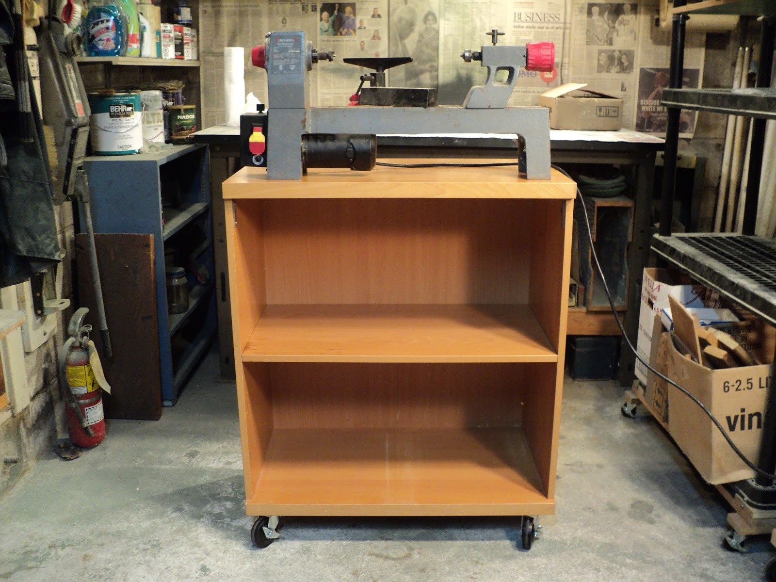
It needs a bit of work, but it may be just what I need for a stand for a Performax mini wood lathe that I hope to be restoring soon. It's 28 3/8" wide by 30 1/2" tall by 15 3/4" deep. With 3" casters[1] added to it, it will be about the right height for a lathe stand.

The unit is of typical, particle-board knock-down construction, which is to say that water exposure is death to it. There's a bit of water damage to the bottom plank at the back. I've filled some unneeded holes in the bottom, and have it ready for sanding now. Here's a view of that.


Once I'm done with the sanding, I'll seal the bottom with a coat of Tremclad clear coat. Then I'll deal with the unit's messed up back panel, and add some bracing and the casters. I should end up with a reasonably good stand for very little money.

- - -

All Done -- SATURDAY, JUNE 10, 2017

Here it is doing what I wanted it to, holding up a small wood lathe. Not a bad outcome for what I paid for it.


* * *

Note:

[1] Busy Bee Cat. No. B17863 -- set of four casters w/brakes.


# # #


# # #


Monday, June 5, 2017

A Leaky Pressure Washer


My son picked up this Briggs & Stratton pressure washer for very little.


The I.D. label on the chassis is mostly obliterated, so I can't tell what the model number is.[1] The engine[2] runs nicely, but it seems that the pump has a bad leak when it's in operation.

To be investigated. This may be interesting.

- - -

It Leaks Alright! -- TUESDAY, JUNE 6, 2017


With the machine not running, but the water supply connected, there's a wicked leak from between the output manifold and the pump head.

The next thing I need to do is to actually run the machine in spite of the leak, just to check whether the pump is otherwise operational. If the pump fails to put out, regardless of the leak, then the washer is a write-off. If pump operation appears to be more-or-less normal, then a repair attempt is worth pursuing.

- - -

'Performed that test, and the pump appears to work. I imagine that the leak is providing a fair bit of pressure relief, and impairing the pump's output pressure somewhat.

Pump Removal

Three M8x40mm hex socket head screws w/flange nuts hold the pump and engine together. You need a 6mm hex key and a 13mm open end wrench to remove them. The pump comes away readily from the engine's keyed shaft.


The pump has a label on it that reads:

MTPV90736
197137
Order 5209923
0511094746

for whatever that's worth.

Here's a view of the leaking spot. The leak is right at the centre of the photograph.


It looks like an O-ring may have blown out. It's time to carefully open up that section of the pump and see what's there.

- - -

And here's the trouble.


An utterly ruined O-ring and a broken screw. I suspect that the pump had a freeze-up incident.

The O-ring is one thing; the broken screw is another matter entirely. The odds of my successfully extracting the broken off screw end are slim to nil.

We'll see what can be done here.

- - -

An attempt to drill out the broken screw only resulted in a broken cobalt drill, so I carved the casting away to get rid of the broken off screw end entirely.


I drilled and tapped what was left of the casting beyond the end of the screw, and came up with a longer M5 screw to replace the broken one. The repair looks like this.


I didn't have an exact replacement metric O-ring, but I had fractional inch O-rings that were close in size. So, I replaced all four O-rings with 9/16" x 3/4" O-rings, so that at least the assembly would close up evenly, with slightly oversize o-rings squashed inside.

Anyway, that worked. The pump no longer leaks, and it operates quite powerfully.

* * *

Notes:

[1] With the help of Google Images I may have deciphered the machine's model number; it appears to be 020288-0, or something very close to that. That makes it a 2008 vintage machine. It's not doing too badly for its age.

[2] Engine is Briggs & Stratton model number 10J902, type 0139 E1. Spark plug is Champion RJ19LM, 13/16" hex, 0.030" gap.

# # #


# # #


Ryobi RY09056 Leaf Blower Carburetor Removal


Carburetor removal on this unit is fairly straightforward.


Proceed as follows:

1) Air Cleaner/Carburetor Cover at Rear
- One tool-less wingnut.

2) Right Side Engine Cover
- Four T20 screws.

3) Tubing
- Disconnect two tubes from the carburetor's nipples.
- Outboard, slightly smaller diameter tube is primer return.
- Inboard, slightly larger diameter tube is fuel uptake.


4) Throttle Cable
- Loosen off one T20 screw securing the throttle cable guide tube. That will give the cable enough slack that it can be disconnected from the carburetor.


5) Air Cleaner Body and Carburetor
- Two 8mm A/F hex nuts.

And that gets you to here.


Note the gasket between the carburetor and the intake tube

- - -

My reason for removing the carburetor here was that the engine wouldn't run at wide open throttle; it would bog down and stall. That was evidence of main jet fuel starvation, so I dismantled the carburetor and blew out all the main jet passages. That fixed it.

How the jet got clogged is a mystery to me; the fuel supply is extremely well filtered.

# # #


# # #


Salvaging Stuff From A Skilsaw Model 3102


I picked up this piece of junk off Kijiji for the sake of the stand. The saw is worthless.


It's an ancient direct-drive 8 1/4" table saw without rip fence or mitre gauge. It runs, but it's scarcely even fit for service as a firewood saw. I'll add it to my collection of stuff that's bound for the scrapyard, but first I'll salvage what bits of it may be useful.

The blade is scrap, but I'll keep the external flange washer and 5/8"-18 arbor nut -- it doesn't hurt to have spares of those.


That red throat insert is a nice piece of steel; I'll keep that as well.

There's a perfectly good 1/4"-20 wingnut at the back, attached to the blade guard mount.


Here's a view of the underside of the saw.


It appears that what Skil did was to take the frame and motor of a portable circular saw, and adapt it to a table saw. The thing still has most of a portable saw's handle on it.

I'll keep the on/off switch. The line cord will make a decent two-conductor extension cord.

- - -

And here's what I've got in the way of electrical salvage.


A little over six feet of 16 AWG two-conductor line cord, a 5/16" cable clamp and a switch. The switch may come in handy the next time that the switch on my Delta midi-lathe gets hopelessly fouled up with dust.

- - -

The elevation and tilt mechanisms yielded a few good bits of hardware.


And that's about it. The rest of the saw is scrap.


- - -

The Stand -- TUESDAY, JUNE 6, 2017

Here it is inside the workshop about to be dismantled.


It's not a bad stand, and I seem to routinely find use for another stand for something-or-other, so I'll dismantle and stash the thing against the day that a need arises. I'll just record a few photos here to help me out with reassembly. (That pegboard panel will likely end up as firewood -- I'm not a fan of pegboard.)


And there we are. One of these days I may have a good use for the thing.

- - -

The Stand Repurposed -- SATURDAY, DECEMBER 15, 2018

I have a spare wire wheel machine with no stand that I'd like to either give to my son or sell, so I decided to put the Skilsaw stand to use as a wire wheel machine stand. I fetched all of the stand's pieces out of storage, gave them a good scrub and reassembled the stand. Here it is holding up the wire wheel machine.


That's not half bad. The stand is about 20" wide x 17" deep x 33 1/2" tall. That 33 1/2" figure is the stand's maximum height. (The height can be reduced by two 2" increments.)

I added a lower shelf from some scrap plywood to give the stand some storage space, and two outriggers to stabilize the stand against any side-to-side 'tippyness'.


I'll prime those wooden parts and paint them light grey, and my wire wheel machine will have quite a decent stand.

# # #


# # #