Thursday, August 4, 2016

A Rockwell/Delta 10" Table Saw


This shabby old saw was in my deceased next door neighbour's garage for God knows how long.


My deceased neighbour's son has sold the house,[1] so he was getting rid of a great deal of stuff. He let me have this old saw for nothing.

 - - -

There's no Model No. I.D. Plate on it anywhere that I can find There's a lot wrong with it. If I can set it right, I'll have a half-decent 10" saw to replace my ancient 8" Beaver. We'll see how this goes.

This is going to be a very disjointed, jumbled up post. It's really only going to be notes on what I'm up to at any given time.

- - -

The single biggest issue with this saw is that it needs new arbor bearings. If I can successfully replace those, then the saw becomes worthwhile to restore to pristine condition. If I fail at replacing the bearings, then the saw is scrap metal. So, I'll start with getting the arbor out.

Removing The Table Insert

The table insert should just slip out easily -- it's theoretically just held in place by gravity. But on this saw, I had to hammer it from underneath bit by bit with a big brass punch to free it; it was somewhat seized in place. The insert appears to be a zinc casting, so it's easily cracked or broken. Here's a view of the thing out of its pocket finally.


It was a fine item in its day, but it's in rough shape now. There's a crack in the edge opposite from the one you can see, and the whole thing is pretty badly distorted.

The Blade

Remove a 15/16" A/F hex nut (RH thread), a flange washer and then the blade.

The Elevation Screw

The elevation screw must be removed in order to be able to remove the arbor assembly. I saw an e-clip on the elevation screw that looked like it might be key to removing the elevation screw, but removing that e-clip got me nowhere -- the screw still would not back off and come out. I'm going to have to get the saw off its stand so I can turn it upside down, and see how the elevation screw really does come out. Once I have the elevation screw out, it should be possible to remove the elevation pivot pin, and then remove the whole arbor assembly. First, though, I have to remove the rip fence, its rails and the table extension to lighten the load.

The Rip Fence

The rip fence just slides off the ends of its rails when it's unclamped.

The Rip Fence Rails And The Extension


Each rail and its spacers is attached with two screws and two nuts.

The extension is attached with three screws w/split lockwashers.

Back To The Elevation Screw

It turns out that I was correct that the e-clip I noticed on the elevation screw was key to removing the screw, it's just that the screw-shaft was balky about leaving through its hole. I put Vise-Grips on it for extra leverage and that did the trick. I got the screw out. Here's a view of it.


There was also a grip-ring to contend with, but that wasn't difficult.

Elevation Pivot Pin and Arbor Casting

Now there's the big elevation pivot pin to be removed.


With its e-clips removed, the pin wasn't too difficult to coax out of place; it wasn't seized. And with that pin removed, the entire arbor casting is free to come out. Here it is.


Now I can attend to the bearings -- the single biggest defect the saw has.

The Line Cord Plug And Wiring

This stuff is in very poor condition, and will have to be replaced.


I'll get a better on/off switch for it too.

The Arbor Pulley And V-Belt

In the following photograph, note the setscrew protruding from the bottom of the pulley's groove, and the groove in the underside of the v-belt.


That setscrew is actually the correct length, it's just that the screw has loosened off almost to the point of falling out; hence the screw's protrusion. And you can see what the screw's protrusion has done to the underside of the v-belt -- it's pretty awful.

Needless to say, a new 40" v-belt is in order. I may go with a link-style belt, if I can scrounge up the money for one.

The Arbor Pulley

Neither the pulley nor the Woodruff key were inclined to leave home. For the pulley's removal, I ended up using a socket wrench for a  punch, so I could punch the pulley further onto its shaft. That dislodged the pulley, then I was able to pull it off with a two-jaw puller without distorting it. The Woodruff key wanted coaxing with a small cold chisel and a hammer. Bit by bit I got it to leave its keyway. Here's a view of those items off their shaft.


That pulley is a precious thing; it has a 17mm bore -- not something I could easily find a replacement for.

The arbor bearing that's now exposed is an NTN 6203LB -- 17mm bore x 40mm OD x 12 mm width. I can get a replacement for that at Princess Auto. The opposite bearing is probably the same, but I won't know that for certain until I've gotten it out.

The Arbor Bearings

With a great deal of hammering, I've gotten the arbor assembly mostly apart. Here's where I am with it presently.


The bearing at the pulley end still feels ok (though I mean to replace it regardless). The bearing at the saw blade end is a ruin and must be replaced.

I'd like to get that bearing off without disturbing the factory installation of the saw blade flange. So, what I may have to do is get the balls out of the bearing, and the outer race off. Then I'd have access to the inner race to grind through it until it eases its grip on the shaft and can be forced off.

'Got It!

The bearing is off.


I had to grind clear through the inner race to get it to where I could force it off the shaft, so I did some very slight damage to the shaft, but it should have no ill effect.

The next thing I want to do is chuck that shaft in the lathe, and check the flange for axial run-out with a dial indicator. If it's perfect, I'll try to install the new bearing from the pulley end. If it's flawed, then I may as well pull the flange off and install the bearing from the threaded end, as it's supposed to be done. (I should have checked saw blade flange axial run-out before beginning, but frankly I wasn't thinking straight -- didn't know what I was doing. Oh well, now I know.)

Saw Blade Flange Axial Run-Out

Here's my setup for checking run-out.


It turns out that axial run-out of the flange is over 0.007"; that's abominable. So, all that bushwah I went through to preserve the factory installation of the flange was in vain. I'll press off the flange, and deal with the run-out after I've installed a new bearing, and reinstalled the flange.

Pressing Off The Saw Blade Flange

Here's the arbor on the press, about to have its saw blade flange pressed off.


And here are the two pieces separated.


That was a breeze, really. The flange pressed off nicely, with no complaints. It may have helped that I had applied penetrating oil to it a few days ago.

Next up is to replace the e-clip that indexes the bearing's axial position on the shaft, and install the new bearing. Then I'll reinstall the flange, and check its axial run-out again on the lathe.

- - -

Bearing And Flange Reinstalled

That went pretty smoothly. I rechecked the flange's axial run-out, and it was 0.001" better than before, but still unacceptable. I sharpened a lathe cutter and turned down the face of the flange; good outcome -- zero (or near zero) axial run-out. I completed reassembly of the arbor, and I appear to have a defect-free arbor assembly now.

This business of machine restoration is more complicated, and fraught with peril, than it may appear. I could still run into a defect that renders the machine worthless -- e.g. blade to mitre gauge slot parallelism impossible to achieve -- so I can't just set off to paint the stand and the chassis as I go, and risk wasting all that work and material. I have to prove the whole machine out first. In a nutshell, here's what I have to do:
  • Fully reassemble the machine, and prove out all of its functionality/adjustability
  • Dismantle the machine for cosmetic restoration.
  • Cosmetic Restoration.
  • Reassembly.
  • Final adjustment/proof.
It's a heap of work, but then it's not as though my Day Timer is loaded with other commitments.

- - -
End Of Part I

This post is getting long. See 'A Rockwell/Delta 10" Table Saw -- Part II' for the continuation.

- - -

Note:

[1] There is, of course, much more to the story.

Bob, my deceased neighbour, was a pillar of the community, and the best next door neighbour one could ask for. He was thoroughly enjoying his retirement, especially his fabulous gardens, when he was struck down several years ago by esophogal cancer. The world is neither a just nor fair place.

Bob and his wife Linda were very close -- always together. After Bob's death, Linda's spirits never really recovered, and her health began to decline. She contracted cancer, was treated for it, and currently resides in a convalescent home. She's not in a good way. She underwent drastic surgery on her jaw, and her recovery process has not gone well.

All of that left Bob and Linda's son, Jim, no choice but to sell the house, which he has done as of this writing. The new owners have yet to move in.

# # #


# # #

My Grimy Old Workshop Coffee Maker Finally Bites the Dust


I have an elderly Proctor Silex coffee maker that I've used for years now in the workshop. I'm not big on washing the thing, so it's not the most hygienic-looking appliance on earth. Here's a view of it.


It's a 'Type A20' -- a basic, basic coffee maker, and it has served me well. (I bought it at Canadian Tire on the 31st of July, 1999.) In my experience, Proctor Silex's small appliances are unbeatable for dollar value and reliability.

But, no matter how good it may be, no appliance is going to last forever, and this one has finally packed it in.

I'd gotten warnings that something was amiss. Every so often, at random, the thing would only deliver a fraction of the amount of coffee for the amount of water I'd put in it. I caught it in the act once, and discovered that it was doing the oddest thing. It was sort of working backwards.

It would deliver some water through the normal route, and brew some coffee, but it would send most of the heated water back into the reservoir where it would steam off in a great cloud.

I gave it a thorough vinegar rinse treatment, but that didn't solve the problem. For quite a while, I just lived with it since the trouble occurred so infrequently.

Then it did it yesterday morning, and again this morning. Enough. The appliance is no longer trustworthy at all. Fortunately, I have a spare Black & Decker unit for a replacement, so my morning coffee ritual can carry on without interruption.

Anyway, since I'll be discarding this poor old soldier, I thought I might dismantle it and, if nothing else, get a look at how it's constructed inside. Maybe I'll learn something.

- - -

Access to the innards is via the underside. There's a metal bottom cover to be removed.


A T15 security Torx driver, and 3/8" nut driver are all that's needed.

And here we are.


There's a clamp-plate affair that holds the whole hot-plate/heater/pump-tube assembly together. Take off the single 3/8" A/F hex nut holding that together, and you get to here.


Supposedly, there's a check valve in these things that's key to the pump's operation. That's probably what's at fault in this coffee maker. Let's see if I can locate the check valve, and see what sort of condition it's in.

There's a bulge in the lower end of the water supply tube (upper tube in the above photo). So I opened that up (the old tubing tore easily) and sure enough, there was the check valve. Here's a view of  the torn-open spot where the check valve resided.


And here's a view of the check valve (or at least what's left of it).


Needless to say, there's no way I can get replacement parts for this coffee maker. I can probably replace the whole thing if I have to (when my Black & Decker unit packs it in) for twenty dollars.

Electrical Components

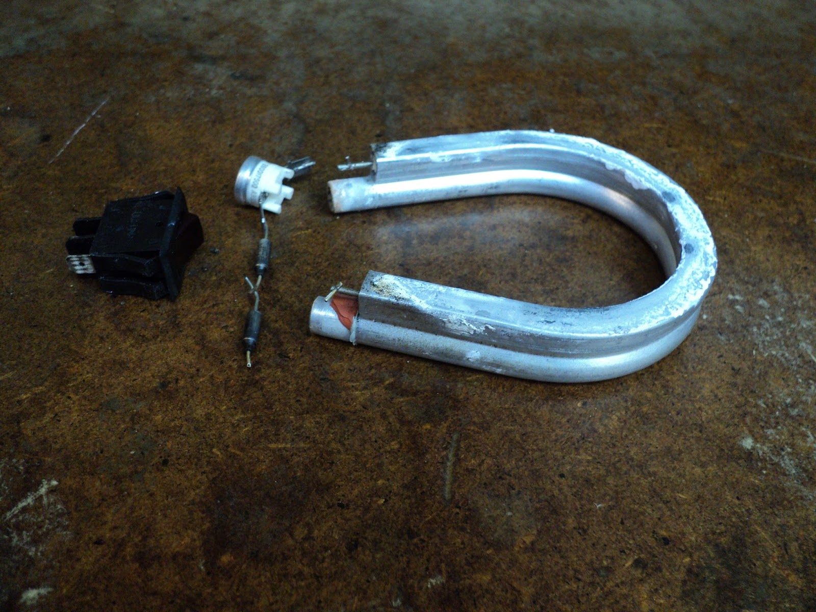
As long as I'm at this, I may as well show and tell about the few electrical components that go into a basic coffee maker. Here's a view of them out of the appliance. (I left out the line cord; a line cord kind of goes without saying.)


From left-to-right we have:
a) An illuminated on/off rocker switch. This one is made by Defond. Defond is a major manufacturer of such things.
b) A series string consisting of two thermal fuses and a thermostat.

The thermostat resides right up against the pump tube. It control's the hot-plate's temperature once a brewing cycle is complete.

The two thermal fuses are a safety feature. In the event of a thermostat failure that results in an over-heat condition, one or both of the fuses will go open. The fuses won't reset themselves. If a thermal fuse goes open, that's the end of the coffee maker.
c) A heating element that's integral with the pump tube. The heating element resides directly beneath the hot-plate. The white stuff smeared on it is silicone grease. The grease is used to improve heat transfer from the heating element to the hot-plate.
And there we are. There's not a whole lot of stuff that goes into the construction of a basic coffee maker.

# # #


# # #

Tuesday, August 2, 2016

Safe Motor Testing Gear


If you have occasion at times to bench-test fractional horsepower motors, you may find these items helpful. I wouldn't be without them.

First off is a switched outlet box with its own line cord attached. Here's a view of the one I made up for my shop.


However you go about constructing one of these, use an unambiguous toggle switch for your on/off switch, and label it unambiguously 'ON/OFF'.

I used a seven-foot, 18AWG line cord. 16AWG would have been better, but 18AWG is adequate for relatively short lengths.

Next up are some quick-connect/-disconnect motor line cords. I have four. First is one with big alligator clips on it, like so.


I didn't have clips with the correct colours of jackets on them, so I have to mind my wire colours when hooking up this cord -- not too difficult to do.

Here's a view of the cord connected to an old brute of a 1/2 hp motor.


In the example shown above, the clips and wires showed no tendency to shift about and short together, so I didn't bother with insulating tape. If a set of connections looks at all 'shaky', then by all means wrap the exposed bits with tape for safety's sake.

My second motor cord is one with two smaller alligator clips for the line connections, and a fork terminal for ground.


Third is a cord with three 1/4" spade terminals on it.


And fourth is a cord with three fork terminals on it.


Those four motor cord configurations will handle just about any motor connection scheme you're likely to run across.

The keys to safe use of the gear are these:
  • An unambiguous, unambiguously labelled on/off toggle switch; preferably one with a high operating force and an accompanying, pronounced 'click'. No mushy rocker switches or push/push switches. You don't want a switch type that might lead to an unwelcome surprise.
  • Apply insulating tape as required if there's any likelihood of connections shorting.
  • Arrange your switched outlet box and cords so they can't possibly get snagged in the works of whatever you're testing.
I find having the five above items at hand is a great time and aggravation saver.

# # #


# # #

Monday, August 1, 2016

An Antique Wagner Electric 1/2 HP Electric Motor


I picked this up from a guy on Kijiji for $20.00.


It's a bit of an antique. I didn't realize how much of an antique until I got it home, and read the I.D. label, and compared it to a modern Marathon Electric 1/2 hp motor. Here's a view of it next to the Marathon motor.


The motor is huge. The Marathon weighs about 15 lbs. The antique weighs about 45 lbs.

Here's a shot of the old motor's I.D. plate.


Following is a transcription of all the I.D. plate data:
  • REP START MOTOR
  • TYPE RPI ['might be RP1]
  • H.P. 1/2
  • R.P.M. 1725
  • CY 60
  • PH. 1
  • FRAME 67Y
  • VOLTS 110/220
  • AMPS. 7.7/3.8
  • HRS. CON 50° C
  • SPECIAL DATA [blank]
  • ORIGINAL MFR. WAGNER ELECTRIC
  • CONVERTED TO 60 CYCLES BY WAGNER ELECTRIC
  • MODEL 248R168
  • SERIAL 127
  • H.E.P.C. CODE P56 04 23-12-790 5003
Following are some notes on the above:
  • Parts of the above transcription are a little iffy. The vertical registration of the data printed on the I.D. plate's grid is poor, and some characters were difficult to be certain of.
  • "REP START" is short for 'REPULSION START'. That's something new to me, and I'll try to learn more in a practical sense. What I've seen on the internet so far looks a bit thick and dense to me.
  • Wagner Electric as an independent manufacturing entity is no more. Here's the Wikipedia entry on Wagner Electric.
  • "CONVERTED TO 60 CYCLES..." says that this was originally a 25 cycle motor, so it's very old indeed. As I recall, conversion to 60 cycles in southern Ontario, Canada occurred in about the early to mid-1950s.
Does It Run?

Yes, it does. It starts and runs quite nicely. It's currently wired for 110V operation. The wiring diagram for voltage conversion inside the connection box's cover is still in fine condition, like so.


The diagram doesn't mention reversibility, so I guess that's not doable. That's ok, though, because the motor's direction of rotation is correct for the application I have in mind. (It's CW, viewed shaft-end-on.)

The shaft has about 0.027" of end play to it, which strikes me as a tad excessive, but it doesn't appear to be a cause for concern. As the motor reaches full speed, the shaft biases itself outward, and seems to be quite happy there.

An Application

I have an ancient Sears Craftsman 8" table saw that I'd like to be rid of. I have other motors for the saw, but if this one will fit the stand I've made for the saw, it would be ideal to go with the saw. We'll see how that goes.

A Trial Fitting

Using this motor with the Craftsman saw appears to be doable.


I'll have to add new motor-mounting tee-nut locations, and possibly get a shorter v-belt, but it looks like it'll work.

I'll put a blade in the saw, clamp the motor in place, wire up the motor temporarily and try the motor under load. If that proves out, then I'll go ahead and make the adaptations to use this motor on the Craftsman saw.

It Works

I put an old thin-kerf blade in, changed the v-belt from 38" to 37", wired it up, clamped the motor in place and gave it a go. It starts up and cuts wood. So now, here's my list of things to be done:
  • Get the pulley off and clean it up, along with the motor's shaft.
  • Remount the pulley and position it closer to the motor's frame. That will minimize belt tension leverage effects on motor bearing load.
  • Establish new mounting bolt locations.
  • Install 1/4"-20 tee-nuts for the new bolt locations.
  • Reassemble everything, tension the belt, wire up the motor and cut some more wood to really give the thing a trial. Fortunately, that existing armored cable that's part of the stand will fit perfectly.
  • Put it up on Kijiji and get it out of my workshop and my life.
Pulley and Shaft

Here we are with the shaft and pulley cleaned up, and the pulley better positioned than it was.


The pulley wasn't badly seized on the shaft, but I did have to use a puller to get it off. The pulley is 5" diameter. The shaft is 5/8" diameter, with a 3/16" keyway.

The keyway had a binding spot in it that I had to file in order to obtain a free-sliding key fit. I think the binding spot was from someone once having tightened down the setscrew with no key in place.

Using the motor as its own lathe, I steel-wooled the shaft and the pulley. The outcome was reasonable. I wasn't after pristine perfection -- I just didn't want the thing to look like it had sat in a barn for the past twenty years.

I gave each bearing oil-hole six drops of 3-IN-ONE SAE 20 motor oil.

Mounting

I got the new mounting hole locations marked out, drilled, counter-bored  and fitted with 1/4"-20 tee-nuts. Here's the arrangement with the motor in place and properly bolted down.


The motor's mounting bolt slots provide a fair bit of adjustment range for belt tensioning. That's a good thing, because belt tension changes depending on the saw blade's elevation, and has to be readjusted accordingly. I've set the belt tension with the saw blade fully elevated, since that's my usual way of operating a table saw.

That saw has a tilt feature, but that will be inoperative with this motor mounting arrangement. Construction of a motor mount that would allow for saw blade tilt would involve a level of engineering skill that's frankly beyond me, so this saw is going to be strictly a 90° cutting angle affair.

Wiring

The wires that emerge from the motor are stranded, like so.


There were wire nuts on those connections that I can re-use for connecting to the incoming armored cable, but I'll want to tin those stranded wires first. When using wire nuts on stranded wire, I prefer to tin the ends of the wires.

And here we are with that done.


Four nicely tinned wire ends that won't shed strands.[1]

A Ground Connection

This motor is from back in the day when armored cable didn't include a separate, bare copper ground wire; the cable's aluminum sheath and a thin strip of aluminum were the only ground continuity guarantors.

Modern armored cable includes a bare copper ground wire, but there's no provision on the motor for connecting it. What I'll do is add a 10-32 stud to a wall of the connection box, and that will serve as a ground terminal.

- - -

And here it is.


That hex nut has an internal tooth lockwasher under it for good measure, and I scraped off paint from under screwheads as required to ensure ground continuity. The motor's frame will absolutely, positively be grounded.

Here's the armored cable installed, the ground wire connected and the line connections ready to receive their wire nuts.


Performance

With everything buttoned up, I gave the saw a brief trial.

The motor takes a full second to get up to speed, which seems a bit long to me -- I'm accustomed to seeing motors reach full speed much quicker than that. Perhaps it's a normal characteristic of a repulsion start motor.

I did a few crosscuts, and one rip cut on a short piece of 2x4, and the motor's power is impressive. I'd say that its 1/2 hp rating is a conservative one. It could probably handle a 1/8" kerf blade easily.

* * *

Update -- WEDNESDAY, JUNE 21, 2017

The saw didn't sell, so I've stashed it away against the day that I maybe enable its arbor tilt feature. We'll see.

I decided that the motor deserved to be better looking, so I tore it down and gave most of it a gloss black paint job. Following is an outline of that whole process and what it revealed of the motor's architecture.

- - -

Two 10-32 thru-bolts hold the motor together. With those removed and the motor disassembled, here's what all we have.

The Wiring-End Bell

It's a lightweight alloy casting with sleeve bearing and capped oiler. I've stripped the paint off it, and I've left it unpainted. It won't rust, and it looks fine unpainted.


Note the round screw-head in a recess at about seven o'clock. That's the head of a screw that fastens the brush carrier angular restraint prong in place for the repulsion-start commutator. More on that in a bit.

The I.D. label on the end bell is the original, from when the motor was a 25 cycles per second machine. Here's a close-up view of that.


That label is also an inspection port cover. It can be swung up for a peek at the repulsion-start commutator. I'll show that when I've got the motor reassembled.

Here's the inside of the wiring-end bell.


Note the rectangular prong sticking up alongside the bearing housing. That's the brush carrier angular restraint.

The Output-End Bell

It's a steel casting with sleeve bearing and capped oiler. I've given it a gloss black paint job.


The Frame/Stator

That got a gloss black paint job as well.


What an unwieldy thing that was to manipulate for painting preparation. Anyway, the outcome is pretty good, except for one little flaw that I'll have to touch up.

I had the frame outdoors for a spell so the sunlight and free-moving air could age the paint and harden it. When I fetched it back in, I noticed a nasty little blemish on it. It's right at the centre of the following photograph.


I have no idea what it is or where it came from -- a wee spatter of bird poop, perhaps. I suppose that's the risk you take with leaving a painted object outside for the paint to harden.

Here's a view of the end of the stator inside the frame.


The stator has a total of thirty-six poles.

The Armature/Rotor

And here we have a repulsion-start/induction-run rotor.


It has twenty poles. The commutator has thirty-nine segments. I don't pretend to understand that.

Here's a view of the rotor's other end, with the centrifugal switch flyweights.


When the flyweights trip outward at sufficient rotor speed, two things happen:
  • The brush carrier is lifted away from the commutator, so the shorting brushes are no longer riding on the commutator.
  • The rotor's segments are shorted together, so the rotor becomes a squirrel-cage rotor.
It's the first I've ever seen of such a start/run arrangement for an induction motor.

Reassembly In Progress -- FRIDAY, JUNE 23, 2017

Here we are with the output-end bell on and the rotor in place, awaiting installation of the wiring-end bell.


Note the groove in the brush carrier at six o'clock. That groove accepts the prong on the inside of the wiring-end bell that anchors the brush carrier against angular motion.

And here's the motor back together, waiting on its thru-bolts and an operational test.


I think that looks fine, with the one end bell bare metal.

- - -

All Done -- MONDAY, JUNE 26, 2017

And here we are with the motor ready to go into service.


I mean to sell it, so I've given it a temporary 18 AWG line cord that's adequate for demonstration purposes. And if I don't get a buyer, that's ok; I'll have a fine, spare 1/2 hp motor on hand that I may find a use for some day.

- - -

Sold It -- THURSDAY, JULY 6, 2017

An ad on Kijiji got results. 'Got my $50.00 asking price for it.

* * *

Note:

[1] See this post for some information on wire connection best practice.

# # #


# # #