Monday, August 1, 2016

An Ultra-Rugged Cart


This was a roadside find.


It's from two doors up the street. The house was sold, and is being renovated. All sorts of trash was out in front, along with this remarkable cart.

The thing is constructed as if for combat duty -- it looks to be indestructible (except for the plywood top). My son conjectured that it may have been originally meant for some sort of institutional application -- in a hospital, perhaps. I think that may well be correct.

The cart appears to have provision for being foldable. Right now, it's too rusted up for that feature to operate.

I'm thinking to restore it as a gardener's patio cart. The height is ideal, and I can construct a new top for it with features useful to a gardener. It will be a fine winter project.

I've Brought It Inside

Between the cart, and the old table saw next to it, I've got work for the winter lined up.


First thing is to stash that loose aluminum edging. Then I want to see how the foldability feature works. Once I have that figured out and operational, I'll delete the ruined, plywood work surface.

Foldability/Collapsibility 

A better word here than 'foldablility' might be 'collapsibility' -- I've discovered that the handles and the work surface can be removed entirely, then the frame can be folded.

Handle Removal

There's a turn-button affair at each handle that serves to retain or release a handle. Here is one in its retention position.


And in its release position.


And the handle removed.


Work Surface Removal

At the rear of the work surface there are two plunger rods. Pulling those rods outward unlatches the work surface's steel frame, and enables removal of the entire work surface, like so.


Frame Fold-Up

With the work surface removed, the cart's remaining framework can be folded very compactly.


The purpose of all that must have been compactness for storage or shipment. Once a cart had a home and a job, there'd be no more point to collapsing it.

Miscellaneous Points Of Interest

Restoring this item to something resembling pristine condition is going to be a huge job with many, many steps to be taken. For me to document it all would be too great an undertaking, and would probably lose the reader's interest in short order. But there are a number of things about this cart that I've observed that might be of interest to some readers, so I'll point them out for those who perhaps share my interest in such minutiae.

Handyman Cotter Pin Replacements

Where have I seen this sort of thing before?


Just about everywhere there was originally a proper cotter pin, that's where.

I like cotter pins, and I hate to see them replaced in the manner pictured above. Here's a brief post I wrote in 2012 about cotter pin replacement. And here's one from 2014 about a refinement to cotter pin installation that can be incorporated into new gear that one may be building.


Mystery Wheels

At the front of the work surface framework there are two small wheels (1 7/16" diameter). Here's a view of them.


And here's a close-up of one.


The wheels' purpose escapes me. I guess, when the work surface assembly is off the cart's frame, the wheels would enable one to roll the work surface assembly around like it was a wheelbarrow. That doesn't strike me as a much needed feature, but I can think of no other reason for the wheels' existence.

British Fasteners

The nuts and bolts that form the axles for the above mentioned wheels have British Standard Fine (B.S.F.) threads. Here's a view of one.
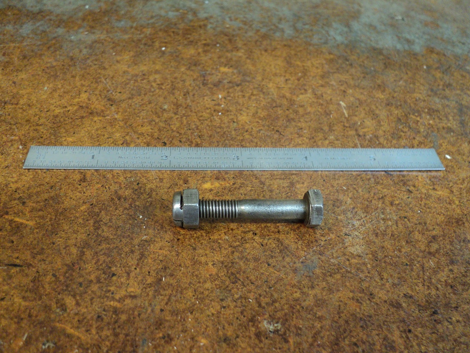

That's a 1/4"-26 nut and bolt. There is no 26 threads per inch 1/4" thread in North American inch fasteners. Also, the A/F (across flats) dimension of the hexes is not 7/16", as it would be for a North American 1/4" nut and bolt -- it's slightly over 7/16", and requires a B.S.F. 1/4" wrench.

1/4"-26 fasteners are used throughout the cart. I think it's safe to conclude that the cart was made in England.

 A Paint Failure

The frame of the cart was painted a creamy white colour, and I meant to strip off what was left of that paint and repaint the frame John Deere green. My first attempt at doing the left side vertical frame member did not go well.

In my experience with chemical paint strippers, their effectiveness can vary widely. Some paint finishes prove to be impervious to the stripper, in whole or in part. (It's a curious thing, but sometimes parts of a finish will strip off readily, while other parts of the same finish will be impervious to chemical stripper. It's the same finish on the same substrate, yet it doesn't respond uniformly to paint stripper. That mystifies me.)

I've grown accustomed to encountering such behaviour from old paint finishes, and when I do encounter it I don't struggle with it -- I just paint over the parts of the old finish that resist being stripped off. My thinking there is that if the old finish is impervious to paint stripper, it should also be impervious to the solvents in fresh paint, so I can safely paint over it without risk of ill effects. Up to now, I've gotten away ok with that approach.

This time was different. Parts of the old, creamy white paint job resisted the paint stripper, but they didn't fully resist the solvents in the spray primer and paint that I applied over them. I was left with a blotchy paint job that would not dry in some places. I had no choice but to strip off my entire green paint job; what a waste of time and material.

Stripping off my paint job left me back where I'd started -- with an old paint job that resisted stripping. Instead of using spray paint again, which would have been futile, I tried using brush-on primer and paint. That worked, because brush-on primer and paint don't contain the same powerful solvents that spray paint does. Here's a view of the frame member with its first coat of John Deere green enamel on it.


(What an awkward thing to paint that is.)

It's not a great paint job. It has brush marks and a few sags, but it will have to do.

If there's a lesson to be learned here, I guess it's to do a spot check when spray painting over old finishes, before committing to the entire job. If the spot check reveals any evidence of bad behaviour from the substrate, then either strip the old finish by whatever means it takes, or try brush-on paint instead of spray. The last thing you need is to have to strip off an entire freshly applied paint job because the substrate was unsuitable.

- - -


Update -- SUNDAY, JULY 16, 2017

'Sorry. I've been remiss in keeping up this blog post.

After a great deal more work, I finally completed the cart. Here's a view of it almost a year later.


It's a far cry from what I started out with. I'm quite pleased with the outcome.

I made the new top for it from cedar fencing planks, and that's held up well so far to the elements.


So, there we are. A satisfactory rescue from landfill or the scrapyard. Instead, a useful and attractive gardener's patio cart.

# # #


# # #

Sunday, July 31, 2016

An Old Saddle Tap


This is probably not worth a salvage attempt.


This saddle tap was on some copper pipe that I picked up from the roadside while out for a walk. The copper pipe was certainly a worthwhile find, but this tap appears to be past it. I only took it off the pipe out of curiosity.

The valve stem is seized. The gland nut has been tightened down all the way, and it appears to have a crack in it, so the valve is unlikely to ever again be leak-free at the stem. But, it's not as though I have anything better to do, so let's at least examine the thing, and maybe learn something about saddle tap failure.

- - -

Here it is fully dismantled.


The gasket is a ruin -- a replacement could easily be made.

The clamp halves and the 1/4" - 20 fasteners are indestructible, and could be wire-brushed back to a decent appearance.

The valve stem and the gland nut are in rough shape; you can see the crack in the gland nut in the photograph. The valve stem's handle is not meant to be non-destructively removed from the valve stem, so that makes servicing of the valve stem and its packing a challenging proposition.

The valve seat is way down inside, and difficult to see to examine its condition, which is unlikely to be good

But just for the heck of it, I'll see if I can drill the handle off from its swage to the valve stem, and get a look at the valve stem's packing.

- - -

On second thought, maybe not. This thing is truly past it. Here's a close-up view of the valve stem portion. (I managed to get the packing washer to reveal itself.)


That packing washer is probably an item that I'll never be able to get a new replacement for, and re-using the existing one is a pretty iffy proposition.

I've spent enough time on this. I'll salvage the 1/4"-20 screws and nuts, and the saddle halves and toss the rest. Some things are just not worth pursuing.

# # #


# # #


Improving A Cheap Set of Forceps/Tweezers


Over at The Whole Garage Catalogue recently, I posted an item about a cheap pair of forceps/tweezers. Here's the post:

- - -

A Pair Of Forceps/Tweezers Of Some Sort


There's no maker's name on them, and they look cheaply constructed. The pivot is a bit sloppy, and the tips align poorly.

With a bit of work, I could improve the thing, and possibly have a useful tool for something-or-other.

I'll stash these in my spare tools drawer against the day that I feel like getting after them.

# # #


Well, I feel like getting after them. So here's what I need to do to improve this tool:
  • Strip off and possibly replace that rotten sleeving.
  • Reconstruct the sloppy pivot.
  • Align the jaws.
Sleeving

That wasn't difficult to scrape off with a utility knife. The tool is reasonably clean now.


I have some red 3/16" heat-shrink tubing on hand that might make excellent replacement sleeving. That can wait until I've dealt with the pivot and the alignment.


The Pivot

The original pivot was a 1/8" diameter rivet. I cut off its end and discarded it.

The pivot holes are slightly oversize -- that accounts for the sloppiness that I observed in the pivot's action.

I can drill out the pivot holes slightly to accommodate a 6-32 screw, but there's a caveat regarding the use of a screw as a pivot pin. It's a very poor practice to have a pivot point operate on a screw thread. You want a pivot point to operate on a full rod/cylinder. So, what I need here is a 6-32 screw that has an unthreaded shank portion that's just the right length to serve as the pivot point, while providing thread enough to be fastened by a Nyloc nut.

I have some 1 3/8" long 6-32 hex socket head cap screws with unthreaded shank portions to them, but the unthreaded portions are too long. So, I threaded one of the screws further, and now I have a screw that should serve nicely as a pivot (once I've cut it down to correct overall length). Here's a view of the screws I've just been on about.


At the left is an unmodified screw. At the right is a screw that I've threaded further. That one's going to be my pivot screw.

The pivot holes need to be enlarged slightly to accept a 6-32 screw, and it's important that I get as close a fit as possible so as to minimize slop in the pivot. Consequently, I didn't just go with the conventional 6-32 clearance drill size of 9/64". I miked the screw's shank, and chose a drill size based on that result.

The screw's shank measured 0.135". The closest clearance drill size is No. 29 (0.136"). So I went with a No. 29 drill, and that gave me just the outcome I was after -- a relatively slop-free pivot. Here's a view of it assembled without a nut.


Now I just have to cut the screw down to correct length, add a Nyloc nut, and my improved pivot will be done.

- - -

And here we are.


A slop-free, reasonably tidy pivot.

All that's left is to lubricate the pivot, align the jaws and add new sleeving.

- - -

Done.


I've got a decent set of forceps/tweezers from what was a piece of offshore junk. Very satisfying.

# # #


# # #


Friday, July 29, 2016

Material Is Where You Find It


A house painting outfit came by a while ago and asked my wife if they could plant a promotional sign on our front lawn. They were doing that all over the neighbourhood. My wife let them, and the sign stayed for days. The painting outfit never came back to retrieve the sign, and I finally pulled it up and stashed it under the carport. Today it occurred to me to dispose of the thing. Here's a view of the sign.


It's a 32" x 20" plastic sleeve affair draped over a skinny steel rod frame. Take away the plastic sign and here's what's left.


About 90 linear inches of 4.5mm diameter steel rod (about 23/128" -- just shy of 3/16").[1]

It's a bit of an odd diameter, but I might find use for it for something-or-other. The price was certainly right.

- - -

Note:

[1] It's undersize for threading 10-24 or 10-32, though I've half a mind to try it and see if I still get a useable result.

# # #


# # #


Saturday, May 21, 2016

Roadside Find -- A Pole Lamp With No Base


This pole lamp looks pretty decent, but it has no base, and the line cord has been snipped off. On the plus side, the switches and sockets all appear to be in operable condition.


There's no maker's name on it, but it does say "Made in China" on the wattage labels inside the reflectors. (Surprise, surprise.)

I can fabricate a new base for it, but there's a little challenge presented where the base attaches to the pole. Here's a view of that.


The jam nut that's needed to secure a base is missing, and that's an odd size of threaded nipple. It's M12 x 1.0mm pitch. I'm unlikely to ever find a nut to fit that. What I may do is remove that brass ring nut from its current location, Loctite the nipple in place at the end of the pole and use the brass ring nut as a jam nut underneath my fabricated replacement base.

A New Base

It would be nice if I could faceplate-turn a wooden disk for a base, but my woodlathe's swing is only 10", and it doesn't have outboard-turning capability. I'd like the base to be about 12" in diameter, so the lamp won't be at all tippy. I'll have to bandsaw a disk, and disk-sand its edges to smooth roundness on a tablesaw disk-sanding jig.

Here's what I have on hand for a base blank.


It's pretty wretched. It's a salvaged motor/grinder mount from an antique grinder that outlived its usefulness. But its thickness is good at 1 1/8", and it's nice and flat. It will have to do.

- - -

And here's my bandsawn blank.


Now I have to rig a circle-sanding jig on my table saw so I can more-or-less 'perfect' the blank's edges.

- - -

And here's a view of the just-completed edge sanding job on my tablesaw.


That's a rude, crude arrangement if ever there was one, but it did the job.

Remaining to be done are the following:
  • Round over the upper edge of the disc to 3/8" radius.
  • Round over the lower edge of the disc to 1/4" radius.
  • Bore through the centre of the disc 15/32" to accept the 12mm nipple.
  • Fill all the holes and surface defects and sand the thing.
  • Come up with a set of 'feet' to elevate the bottom face of the disc up off the floor. That will provide clearance for the bottom end of the nipple, and the emergence of the line cord.
  • Prime and paint the disc flat black. 
- - -

And here we are with some progress made.


Here's a view of the fastening underneath.


(Note the oversize flat washers both top and bottom. Those are absolutely essential to achieving a firm, reliable wood-to-metal attachment of the pole to the base.)

Next up is to make a set of eight feet for it. I was hoping that Canadian Tire might have suitable ones made of black plastic, but I came up empty there. Making plastic feet would be an ideal job for a 3D printer, but I don't have one of those. I'll have to fabricate feet out of hardwood on the lathe.

- - -

Feet

This won't be easy. As a trial effort, I made one sample of what I'm after, like so.


That was turned from a short length of 3/4" dowel held in a chuck on the wood lathe. After turning the taper, I bored it through and counter-bored it for a fastening screw. Then I parted it off. And that's where a snag arises.

Parting off multiple pieces to an exact, consistent length is not easy. I could make eight feet by the same method, but I'd be unlikely to succeed at getting them all parted off to exactly the same 5/8" length. A different approach is called for. Here's how it'll have to go:
  • Set up a length registration jig on the table saw to cut eight pieces of dowel to the same length.
  • Bore through each dowel piece on the metal lathe 9/64" -- clearance diameter for a No. 6 fastening screw.
  • Counterbore each dowel piece on the metal lathe 5/16" for the heads of the fastening screws.
  • Fabricate a mandrel that will allow me to mount each dowel piece on the wood lathe for turning the taper.
Here's my length registration setup.


It's just a scrap board clamped to the saw's table the right distance from the blade. Note that the board is positioned so that the work leaves the board before it enters the saw blade. The board must not be positioned so that the work could get pinched between the board and the blade.

And here are my equal-length foot blanks.


I cut one extra one in case I happen to botch one.

- - -

And here they are bored and counterbored.


Next up is the challenging part -- to create a suitable mandrel so I can turn a taper on those feet between centres.

- - -

Here's my mandrel.


Now we'll see what sort of result I can wring out of this.

- - -

And here we are.


Eight tapered feet, all the same length.

I can't say that I did a superb job of that. My mandrel fixture left a bit to be desired, and I wasn't trying all that hard for perfection, but the result is acceptable for the purpose.

I'll do a trial installation of those feet on the lamp's base. Then I'll attend to the lamp's line cord, and complete a trial assembly of the entire lamp. Once all that has been done, I can dismantle the thing and carry on with sanding the base, and priming and painting it.

- - -

And here's the completed lamp, ready for service.


That's not exactly its natural habitat, but it was the best place I could find to photograph it.

Here's a close-up view of the base.


The base is not absolutely flawless; if you look closely enough, its 'chunk-of-wood' origin does show through a little. But from the distance it's normally seen from, it's a perfectly acceptable lamp base -- a good example of what can be wrought from some pretty wretched salvaged material.

And here's a view of the finished underside, with the feet attached, and the line cord's emergence dealt with


Note the following:
  • The feet are attached with No. 6 x 1" round-head wood screws. It's a very firm attachment that's not going to work loose.
  • The M12 jam nut is very firmly tightened.
  • The line cord is sleeved with some tough, clear plastic sleeving where it exits the nipple.
  • The line cord is secured to the base by a cable clamp for strain-relief.
  •  The 5/8" height of the feet provides more-than-enough clearance for the nipple attachment, and the line cord's emergence and strain-relief.
All-in-all, I appear to have done a pretty decent job of getting this discard back into useable, reliable condition.

Lamps

The labels inside the reflectors call for 60 watt maximum R20 bulbs. At the dollar store, I found 50 watt halogen PAR20s for $2.00 each. (By the way, here's a good explanation of what 'R20' and 'PAR20' are all about.)

LED equivalents are now widely available, and the prices, though still rather high, are within reason. The halogen bulbs do have the advantage of being dimmable; that could be a very attractive feature, depending on how this lamp ends up being put to use.

# # #


# # #


Tuesday, April 12, 2016

Waxed Paper 'Washers' For Finish Protection


If you attach anything securely to a painted or varnished surface, the attached thing is likely to 'weld' itself to the surface tenaciously, no matter how well hardened the finished surface appears to be. Future removal of the attached thing will result in damage to the surface underneath. That may or may not matter to you, but if you'd rather preclude such damage, install waxed paper 'washers' at the interface of the attached thing, and the painted or varnished surface.

I recently removed the mechanic's vise from my workbench, so I could refinish the workbench's hardboard surface with polyurethane. Where the vise base's mounting washers had been in contact with the bench, the washers had bonded themselves to the bench with a vengeance. The washers came away with great shards of hardboard stuck to them, like so.


I filled in the damaged spots on the benchtop, refinished the bench's surface and cut three waxed paper washers for the reinstallation of the vise.


And here we are with the vise's base bolted back in place.


The reason for placing washers underneath the vise's swivel-base mounting ears is to preclude breakage of  the swivel-base casting. Tightening down a cast swivel base directly onto a benchtop's surface is unwise -- irregularities in the surface, and/or the casting, can result in stresses that may break the casting. I've seen it happen. The washers serve to concentrate all the attachment force directly at the ears, isolating the rest of the casting from untoward forces.

# # #


# # #

Saturday, April 2, 2016

On Salvaging Old Gear


On the face of it, salvaging old gear of any kind seems like a paying proposition. Retail prices of anything new these days are sky high, and are unlikely to ever come down. But are there really savings to be had in salvage?

Much as I'd like there to be, and much as this blog has often featured salvage projects as subject matter, I'm not so sure that salvage effort is always, or even often, worthwhile.

Over my years of servicing laser and impact printers, and working closely with printer subassembly remanufacturing operations, it dawned on me that there seems to be nothing quite like factory 'newness'. No matter how meticulously an old mechanism is refurbished, its service life and reliability are unlikely to equal those of new replacements.

Anyway, for want of anything better to do, I thought I'd refurbish an old water supply shut-off valve, and test it out to see if it could still be trusted to give leak-free service. Here's a view of the valve.


It's a common 1/2" copper pipe to 3/8" compression fitting shut-off valve, as is typically installed for a faucet's water supply. This one appears to have been installed by a DIYer -- there's evidence of some sort of sealant having been applied to places where there ought to be no need for sealant. DIYers are notorious for gratuitous application of sealant.

I'll clean it up nicely, and devise a test fixture. If it doesn't leak at its valve stem when fully opened, I'll consider my refurbishment to have been a success.

Following are a few noteworthy points:

Washer


The washer in this type of valve is not replaceable. Water supply shut-off valves are so seldom closed that washer wear is not an issue. An embrittled, cracked washer would spell the end of a valve's usefulness, unless one wanted to undertake the machining necessary to make the washer replaceable.

The Valve Seat

Like the washer, the valve seat is not replaceable. A corroded valve seat (unlikely) might be salvageable by reaming and/or burnishing with valve-grinding compound. See this post.


Valve Stem


The valve stem ought to be cleaned with fine steel wool prior to removal of the gland nut and seal. One wants nothing to abrade the lip of the valve stem's seal as the seal is removed.

The 1/2" Copper Pipe Socket


I've been meaning to acquire a 5/8" reamer to help me salvage 1/2" copper pipe fittings, but the price has been scaring me off. Meanwhile, I've been making do with an X-Acto knife and steel wool.

The socket must be clean, and must easily accept a pipe end to the full depth of the socket.

The Valve Stem Seal


There are two parts to the seal -- a thrust washer, and the ring-seal itself.

The thrust washer is concave; the concave side goes outboard. The ring-seal is asymmetrical face-to-face; note its orientation as you remove it.

The ring-seal must be resilient and undamaged, else the valve is a write-off. The seal pictured here looks a bit distorted on one side; it remains to be seen whether that will be detrimental.

Note the discolouration of the valve stem near the stem's thread. That's evidence of slight corrosion that may cause stem sealing to be iffy.

The Test

I assembled the cleaned up valve, using silicone grease on the valve's threads, and all its stem-sealing surfaces. I rigged a test fixture that allows me to install the valve onto a faucet that has a 3/4" hose-fitting thread on it. Here's a view of the valve in 'operation'.


The photo shows the valve pressurized and fully opened. The valve's output end is closed, as it would be if it were supplying a closed faucet.

It looks good. There's not a hint of weeping at the valve stem.

So, that turned out well. It would be safe to put that valve in operation in an actual faucet installation.

# # #


# # #