Thursday, August 29, 2013

A 6" Bench Grinder Restoration


I just brought this over from the garage.


It's a fine piece of gear, and the bearings appear to be ok.

Aesthetically, though, it leaves a bit to be desired. I'll tear it down and refinish it, then come up with a stand and a motor for it. If and when my son goes and does something silly like buying a house, it can be his house-warming gift from dad.

- - -

Teardown Sequence

1) Right Side Wheel
- One 15/16" A/F hex nut (5/8"-18)
- One 1 3/4" (nominal) diameter flange.
- Wheel (w/bore bushing if present).
- One 1 3/4" (nominal) diameter flange.

2) Left Side Wheel
- NOTE: You may need to restrain the spindle from turning while dealing with this item. A good way is to half-wrap the right side end of the spindle with a scrap of aluminum sheet metal, and clamp down on that with Channellocks.
- One 15/16" A/F left-hand-thread hex nut (5/8"-18)
- One 1 3/4" (nominal) diameter flange.
- Wheel (w/bore bushing if present).
- One 1 3/4" (nominal) diameter flange.
- One 9/16" long, 5/8" bore spacer. (This item is peculiar to this particular bench grinder, because of the fairly wide wire wheel that is the left side wheel. The spacer is to keep the right side perimeter of the wire wheel clear of the guard.)

3) Two Tool Rests
- Two 1/4"-20 x 1/2" square head, cup point setscrews (1/4" A/F).
- Tool rest rectangles are approximately 1" x 1 5/8".
- Shanks are 3/8" diameter x 1 1/4" long.

4) Two Tool Rest Arms
- Two 1/4"-20 x 1/2" A/F hex nuts.
- Two 1/4"-20 x 1" carriage bolts. (I may use slightly longer carriage bolts at final reassembly, so I can add flat washers and split lock washers.)
- Two tool rest arms.
- NOTE that the arms are interchangeable.

5) Two Wheel Guards
- Four 10-24 x 1/2" round head, plain slot screws.
- Two wheel guards.

6) Pulley Setscrew/Spindle w/One Bearing/Pulley/Belt
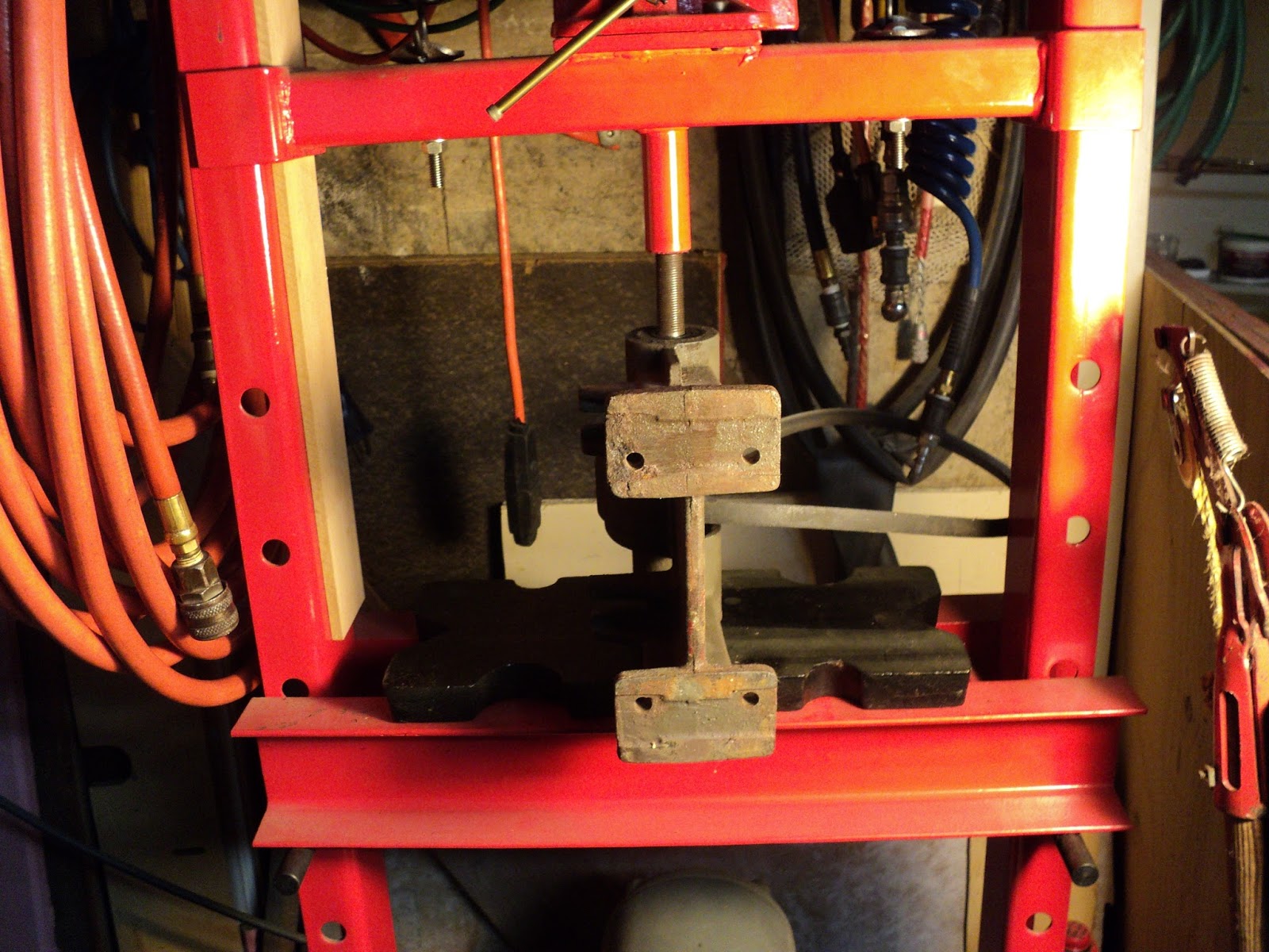
- NOTE that a press is essential for this step.
- Pulley setscrew -- remove it. It's 1/4"-20 x 1/4" cup point; 1/8" hex socket.
- Set up the machine in a suitable press, and press out the spindle w/one bearing.
- Pulley (2" diameter; 3/4" bore).
- Belt (BANROPE A-31A).

The bearings are No. 6203, sealed both sides.

Here's a view of the chassis in my press. I've just begun, here, to press out the spindle.

7) Remaining Bearing
- One setscrew at front of casting -- 1/4"-20 x 1/4" cup point; plain slot.
- With a suitable length of suitable diameter hardwood dowel for a ram extension, press out the remaining bearing.

Here's what you end up with.


That's everything. Now I can clean up and refinish each piece prior to final reassembly.

(Note that the only way to get the R.S. bearing off the spindle is to press it off. That bearing is an interference/press fit on the spindle.)

I'll add a photograph of the finished machine here when I'm done. Also, I'll show what's involved in reinstalling the spindle and bearings -- that's a bit more intricate than taking them out.

- - -

A Bearing Installation Tool -- MONDAY, SEPTEMBER 30, 2013


Pictured is the tool I turned from hardwood for re-installing the bearings in the chassis. O.D. is 40mm, same as that of the bearings; bore is 5/8". Length is 2 3/4". Length is not critical; the adapter only has to be 'long enough'.

I've painted all the components of the grinder. When the paint has had sufficient time to fully harden, I'll get on with reassembly.

- - -

Reassembly Notes -- SATURDAY, OCTOBER 5, 2013

There's more to reassembly than meets the eye. The R.S. bearing is an interference/press fit on its spindle seat. That dictates an order of reassembly that must be adhered to. Following are some observations concerning the fits of the bearings with respect to the spindle and the casting:

a) The R.S. bearing is an interference/press fit on its spindle seat. It must be pressed onto the spindle first to begin reassembly.

b) The L.S. bearing is a free, but very close, fit on its spindle seat. When presented to its seat by the face of the tool, it can be slipped onto its seat by hand.

c) The outer races of both bearings are a 'tap-in' fit in the casting. Relatively light hammer taps will set them in place.

Note: DON'T FORGET THAT THE PULLEY AND BELT MUST GO ON THE SPINDLE AS IT'S INSERTED INTO THE CASTING.

With the spindle and R.S. bearing together, install that assembly in the casting with the aid of the tool.

Again with the aid of the tool, install the L.S. bearing. Some 'toing and froing' from side to side may be necessary. It actually would have been helpful at times to have had two of the tools, one to use as an 'anvil' under the R.S. bearing while the L.S. bearing was being installed.

Once satisfactory bearing installation has been achieved, install the setscrew at the front right side of the casting. Here's a view of what you'll have.


The remainder of the reassembly is straightforward -- it's simply the reverse of the teardown sequence.

- - -

Back In Business -- THURSDAY, APRIL 24, 2014

Here's a view of the completed restoration, powered by a salvaged 1/3 hp motor.


It's quite a nice piece of workshop gear.

This style of grinder has one slight advantage over the integral motor types -- there's no bulging motor in the middle. That can be advantageous when dealing with some clumsy pieces of work; there's a little more open space in which to manipulate work.

On the right side there's a new Norton 6" x 1/2" medium grit wheel. It's a pretty fine 'medium', so that will serve as a fine wheel.

On the left side I've temporarily installed a 5" x 3/4" wheel -- that's all I have on hand. What I'd like to get for the left side is a very coarse, very aggressive 6" diameter wheel for fast material removal. I think that combination of wheels would make for a really versatile, useful bench grinder.

Anyway, it runs nicely, and I'm pleased to see it back in service after many idle years.

# # #


# # #

Sunday, August 25, 2013

A Pressed Leaves Frame Repair


Yeehah! The workshop has received a commission. The lady next door brought me a glass-framed,  'pressed leaves' artwork that's in need of repair; one of its soldered hanging eyes has come away, like so.


What I'll have to do here is get that bare patch of copper frame perfectly clean and bright, then pre-tin it with solder prior to the final resoldering. Pre-tinning is the key to success here, and would have precluded this failure had it been done when the frame was first made.

- - -

This will work fine.


I deleted the extra bit of copper that was soldered to the eye. There's no need for it, and the other side doesn't have one.

The only difficult thing here will be rigging a means to hold the eye in place for soldering. Once I find a good way to do that, the soldering will be easy.

MaƱana.

- - -


A Soldering Clamp Rigged -- TUESDAY, AUGUST 27, 2013

Here's what I came up with for a soldering clamp.


That's a spread-open paper clip and a rubber band.

The solder's adhesion to the paper clip will be negligible -- the paper clip will break away easily. The only downside to this method is that there will be a slight flaw in the appearance of the finished solder fillet. Here's a view of the result with the flux residue cleaned away.


That 'groove/ridges' in the solder is the flaw that I mentioned. All things considered, the flaw is quite tolerable, and the soldering clamp did away with what could have been a great deal of aggravation.

Anyway, that's a sound solder joint that will last indefinitely. Here's a view of the entire artwork.


A little patch of summer/autumn to have in the house for when the snow and ice are piling up outside.

# # #


# # #

Saturday, August 24, 2013

A Button Repair


[Things have been a bit slow around here while I try to learn how to cope with my bleeped up health. This item is representative of the level at which I'm able to function lately. At least it's something, which is more than I've done for quite a while, now.]

- - -

This lady's bag has a purely decorative button on it with a fabric-covered, snap-fit cap. The cap came off, and doesn't want to snap back on securely.


I could push the cap back on as best as it will go, then apply CA adhesive around the cap's perimeter. That would work, but the CA adhesive will wick up into the cap's fabric covering and discolour it.

An alternative is to adhere the cap in place with a blob of silicone sealant. I think I'll go with that idea, but before I do, I'd best 'adjust' the button so the cap fits on easily. If I have to struggle with the cap, I'm liable to smear some silicone sealant about and make a mess.

- - -

Here's everything ready.


I installed a paper mask, just in case there's any squeeze-out of silicone sealant. Here goes final assembly.

- - -


That turned out ok. I'll set the bag aside in a safe place for the sealant to cure overnight, and that'll be a done deal.

- - -

How about that? I did a smidgen of useful work today.

For tomorrow, I have a little soldering job lined up. We'll see how I make out with that.

# # #


# # #

Sunday, July 28, 2013

A Pin Vise Improvement


I brought this over from the garage.


It's quite a nice pin vise, but it has a flaw -- the handle isn't pinned to the chuck's spindle, so the handle will turn on the spindle if it's forced enough. I often use a pin vise as a tap wrench, so that won't do.

Here it is taken apart.


I think I see what happened when my dad was making this.

He'd meant to pin the handle, and began drilling through, but the hardness of the spindle defeated him. (I tried a file on that steel, and the file wouldn't touch it.) He then tried for a shallow, partial pinning, but didn't quite get what he was after.

There's an existing 3/32" hole through the spindle. If I can get that short pin out of the handle's ferrule, there may be a way I can exploit that.

- - -

Progress

I got the 'pinlet' out of the ferrule, and here's where I am with the handle/spindle interface now.


The hole in the ferrule is 1/8". The hole through the spindle is 3/32". I can go either of two ways with this.

a) I have cobalt drills. I can risk a costly cobalt drill in that incredibly hard steel, and maybe drill through 1/8", and then install a 1/8" roll pin or equivalent.

b) I can drill through the other side of the ferrule 3/32", install a 3/32" roll pin or equivalent, and then back fill the remaining oversize hole in the ferrule with epoxy.

I think I'll go with 'b)' -- 'b)' will work well enough, and it can't cost me a drill.

- - -

Here's a view of a pin's trial installation.


I got that pin from the shank of a broken 3/32" twist drill. See this post for my method of cutting very hard steel items like that.

Needless to say, I don't have an interference fit here, so I'll install the pin with CA adhesive.

- - -

A Method For Forming An Epoxy Fill

The pin vise's handle has an 11/64" hole through it for hanging it on a nail. Where the drill emerged, there was some splintering out that I 'd like to correct, so I'm going to try something here that I've been meaning to try out. Here's what I've done.


I smeared the shank of an 11/64" twist drill with WD-40, placed the drill in the hole and laid on the epoxy around it. I'm thinking that once the epoxy has fully cured (overninght, even though it's the five-minute stuff), I should be able to knock the drill out fairly easily, leaving behind a fill that exhibits a nice clean hole. We'll see how this works out.

- - -

It worked.


Now I just have to file away the excess epoxy.

- - -

That turned out remarkably well.


At the ferrule, you can see the back-filled, oversize pin hole.

(I sanded the thing in the lathe a little -- that's why it looks so dull. I mean to paint it dark blue.)

The handle is bored all the way through. I'll fill that bore with dowel, and drill a 5/32" hole in the end. That will be the chuck key's parking spot when the tool is idle, hanging on a toolboard.

- - -

All Done


There we are -- always at the ready, and I know where its chuck key is.

I mentioned earlier that I often use a pin vise as a tap wrench for small taps. If the chuck tends to unscrew when I'm doing that, I'll install the chuck with blue thread-locker.

# # #


# # #

Saturday, July 27, 2013

A De-Laminated Pot Handle Insulator


The two insulator halves are undamaged, it's just that the factory's adhesive took early retirement.


I'm tempted to use CA adhesive for this repair, that would be quick and easy, but CA adhesive is not all that heat resistant.

A better choice might be Permatex Ultra Grey gasket maker. That stuff will be up to the job for certain.

- - -

Here are the parts ready for reassembly.


And here's the insulator gently clamped up for the Permatex to cure overnight.


That should be a good, permanent repair.

* * *

Not Quite -- FRIDAY, OCTOBER 10, 2014


The repair lasted for over a year, then gave up the ghost.

What's obvious to me now is that the Permatex gasket maker doesn't truly adhere to the plastic -- it peels away quite readily.


I suspect that the plastic is of the sort that nothing will truly adhere to.

Hmmm.

I'll re-glue the insulator halves using CA adhesive this time, and see how that holds up. If that fails, I'll be left with no choice other than to install through-fasteners. That will give me a permanent, albeit inelegant, repair.

- - -

Here it is glued and clamped up again.


I'll give that twenty-four hours for the glue to cure, then I can return the pot to service and see how long this repair lasts.

# # #


# # #

Sunday, July 14, 2013

Swaging A Distorted Hose Fitting Seat


* * *

[An aside -- 'swage'[1] is a slightly problematic word. See the footnote.]

* * *

We have a garden hose nozzle that's a pretty decent unit of its kind, but it has a problem -- the seating flange in its hose fitting is distorted, and it won't seal properly. The likelihood of my succeeding at repairing the thing may be slim-to-nil, but I'll give it a try. Here's a view of the hose fitting end of the nozzle in the vise.


The distortion is by the rear jaw of the vise -- the flange is lifted there; no washer can compensate for a distortion like that. I'll see if a brass punch can have any good effect on it.

- - -

A 7/32" punch, followed by the back end of an 11/16" socket wrench, got me some iffy-looking progress, like so.


The flange is light gauge aluminum, and it tore in three places, but I think I can make this work.

A ball-valve goes with this nozzle, and the ball-valve can be permanently attached. I'll install the ball-valve with a high quality orange rubber washer and Permatex Ultra Grey sealant. That should get the nozzle back to a useable state.


I'll just have to be careful to tighten the fitting with the ball-valve's lever correctly oriented for convenient operation -- the fitting will no longer be readily adjustable with cured sealant in it.

- - -

So far, so good.


Tomorrow, I'll add the quick-disconnect and try it out.

- - -

Working Fine -- MONDAY, JULY 15, 2013

I hooked it up and it's back in good order. Here's what the whole unit looks like.


- - -

Note:

[1] Whenever I write 'swage' on blogger, I get the red, squiggly underscore indicating a misspelled or non-existent word. 'Swage' is a proper word. Here's a tangible example of a 'swaging' tool.


'Swage' is a perfectly good English word. I may tend to use the word a bit loosely, but I don't think I'm guilty of having used it incorrectly here. What I did here was I 'swaged' the hose fitting's seating flange down into place.

# # #


# # #

Saturday, July 6, 2013

A Battery Compartment Cover For A Lego R/C Dune Buggy


Pictured below is a garage sale find.


My son picked it up for very little. It's in fine condition and complete, except that it's missing its battery compartment cover underneath. Here's a view of that.


This may be a bit challenging; we'll see how it goes.

- - -

I have some 0.024" thick aluminum that will serve for a cover. The most intricate part of this will be the cover's rear edge, so I'll start with that. Once I have that so it fits, I'll cut a rectangle the correct width from the oversize piece of aluminum stock, and the remainder of the work ought to be fairly straightforward.

Here's a view of the rear edge's layout done on masking tape.


I can cut most of that with a nibbler, then file to the layout lines.

- - -

So Far, So Good


The rear edge fits perfectly.

I'll finish this tomorrow. The union here doesn't like me to work overtime.

- - -

Front And Rear Edges Both Fitted -- SUNDAY, JULY 7, 2013

The front edge turned out to be a bit of an ordeal; it needed two shallow notches to accommodate the two latches. That took a fair amount of trial-and-error filing to get it right. Anyway, it's done now.

The remaining edges are simply a flush fit to the perimeter of the battery compartment, so I just have to trace the outline from above, and cut it with snips.

- - -

All Cut To Shape

It's nearing completion.


I tried it out with the battery inside, and that 0.024" thick aluminum appears to be quite adequate for the job.

I'll laminate fish paper[1] to the cover's upper (inner) surface with double-sided tape, both for the sake of electrical insulation (not that it's really needed), and to lend the cover a little extra strength. The good effect that lamination has on the strength of thin materials is remarkable.

- - -

Fish Paper Lamination Done And Painted -- MONDAY, JULY 8, 2013

I hadn't meant to paint the fish paper side, but my ancient roll of fish paper was badly discoloured, and looked awful, so I painted it 'camouflage khaki'. Here's a view of that.


[It says 'camouflage khaki' on the spray-paint can. It looks like a pretty good facsimile of 'light/medium grey' to me. Whatever.]

I'll let that paint harden for a day or two or three, then I'll do the flat black painting of the underside, and this thing will be well and truly done.

- - -

Fully Painted, But With A Revision -- SATURDAY, JULY 13, 2013

The light colour on the upper surface turned out to have been a mistake -- it showed a little at the sides and didn't look right. So, I made the cover flat black all over, and added an 'UP' label to the insulated side, like so.


And that's as done as it's going to get. Here's a view of the car with the cover in place.


- - -

Another Revision -- TUESDAY, JULY 16, 2013

My son pointed out a potentially misleading characteristic of the 'UP' label I added to the insulated side of the cover. Consider --


To access the battery, one turns the car upside down. It would not be wildly illogical, then, to replace the cover with the word 'UP' facing 'up' -- i.e. ultimately upside down.

I guess the simplest fix for that would be to replace 'UP' with 'IN', like so.


There; that should take care of that.

- - -

Note:

[1] Fish paper is a tough, thin (0.010") elecrical insulating material. I tend to think of it as belonging to the days of vacuum tube electronics, but it's still used and is still available. Why it's called 'fish paper' is a mystery  to me; it neither looks like nor smells like fish. Were I to go fishing, it wouldn't occur to me to take any fish paper with me. Were I the proprietor of a 'fish & chips' establishment, I wouldn't serve fish & chips wrapped in fish paper -- that's what newspapers are for, like so.


If anyone knows why 'fish paper' is called 'fish paper', I wish they'd explain it to me.

# # #


# # #