Thursday, March 14, 2013

Flaky LED Flashlights


* * *

[Update -- WEDNESDAY, OCTOBER 16, 2013

Since I wrote this post, I've seen evidence to suggest that there may be more to LED flashlight flakiness than meets the eye, and that I may have been mistaken in my diagnosis of the cause of it. I'll leave the post in place below as I originally wrote it, but be aware that it may be fallacious.]

* * *

I'm a big fan of LED flashlights; I have a bunch of them that my son got me for Christmas two years ago. I think they're the neatest thing since the Ford 8N tractor.

However, as with all electro-mechanical devices, LED flashlights can exhibit misbehaviours. Two of my small flashlights had the annoying habit of dimming, or going out altogether now and then. A rap against a hard surface would get them back to full brightness, at least until they'd randomly dim or go out again. As it turns out, there's an explanation for why they were doing that, and there's a fix.

Here's a view of the two troublesome flashlights.


The key to this is the manner in which the head-end of the flashlights is assembled; the clear 'lens' is a 'snap-fit' part that retains the little LED array circuit board assembly inside, and establishes its electrical connection to the metal shell of the flashlight. Using a 3" length of 3/4" copper pipe as a 'punch', the whole business can be dismantled with a tap from a light mallet, like so:


Note two things -- the three spots of solder at the periphery of the circuit board, and the un-anodized (bright, uncoloured) ledge inside the flashlight's red shell. That's where the battery current circuit is made between the LED array and the shell of the flashlight. If the circuit board is not pressed tightly against the naked metal ledge, the flashlight will be flaky.

Anyway, so much for 'show-and-tell'. The upshot of all that is that there's no need to dismantle one of these little flashlights in order to fix it. All it takes is to punch the LED array down tighter, like so.


Strike the periphery of the lens lightly and evenly all around to firmly seat the LED array's circuit board against the naked metal ledge inside, and the flashlight will work reliably.

- - -

Update -- SUNDAY, APRIL 21, 2013

The trouble recurred on the red flashlight. These things have a design flaw -- the battery contact at each end of the battery is a coil spring, applying its force in exactly the direction likely to unseat the LED circuit board from its contact ledge. I punched the lens down again, and that got the flashlight working again, but I'll have to give some thought to a way to correct the flaw permanently.

# # #

Sunday, March 10, 2013

Aids to Layout and Centre Punching


My near vision is not what it used to be. I'm in no hurry to get reading glasses, though, because I can still read ok, and because getting reading glasses involves business and commerce, and I loathe business and commerce. However, moderately precise work with centre punches and the like can be a bit challenging. Here are a few things I've found helpful.

Masking Tape

Masking tape is a great layout medium for metalworking, and even woodworking at times. Here's an example of its use for spotting a hole location on a small piece of steel flat.


Note the two centre punches. The smaller one I keep finely pointed and sharp. The larger one is relatively a bit blunt.

Illuminated Magnifier and Black Marker


What I do with the black marker is I blacken the tip of the fine centre punch. That has a remarkably good effect on my ability to see the tip of the punch clearly. Here's how I proceed:

a) Hammer ready next to the back of the vise.

b) Viewing through the magnifier, I get the point of the punch positioned at the intersection of the lines, and press the point lightly down on the tape. That gives me a non-skid dimple in the tape that will retain the punch point's position, while I carefully move the work and the punch together to the back of the vise.

c) My left hand takes over holding the punch. I pick up the hammer with my right hand and strike the punch. Here's the outcome.


Maybe not perfect to within 0.0005", but not bad at all -- probably far better than I would have done without the aid of the tape and the blackened punch point.

I follow up with the bigger, blunter centre punch, and I've got a punch mark that will get a pilot hole started truly.

The fine centre punch's tip must be re-blackened for each use. On large work, have the work well lit, and use a hand-held magnifier to achieve the same effect.

# # #


# # #

Saturday, March 2, 2013

Household Dashboard Instrumentation


[Every so often, I like to tackle some little project that really, truly needn't be tackled. This post sheds some light on why that is.]

* * *

The other day, it came to mind that I have this gorgeous old Smiths oil temperature gauge that's been sitting idle in a box for decades. Here's a view of it.


It's an item I acquired in my adolescence that I never got around to installing in a vehicle. (As for why I ever thought I needed an oil temperature gauge, let's just say that it seemed like a good idea at the time, and leave it at that.)

The gauge is a proper Bourdon tube type with a sensing bulb and capillary tube. I could try to sell it -- it seems these classic gauges are worth a few bucks -- but I'd rather enjoy the use of the thing. I could install it in my truck, but I really don't feel like doing that. So, what to do with it? How about installing it as a furnace hot air plenum temperature gauge? I think that would be a fine thing for a house to have.

- - -

Things I'll Need

  • A mounting panel for the gauge.
  • A flange to fit the sensing bulb to the sheet metal wall of the plenum.
  • A power source for the gauge's light bulb.
- - -

The Mounting Panel

I have a piece of brushed aluminum salvaged from an old impact printer that will serve nicely for panel material. Let's see what I can do with this.


This part is a pretty straightforward thing to fabricate. I should point out something about the use of a fly cutter, though. Here's a view of the setup I used for cutting the 2 1/32" diameter gauge hole.


Whatever it takes, the work must be absolutely, positively secured. Your hands are not to go anywhere near the work while the fly cutter is in operation. Use your machine's lowest spindle speed. Slow and easy feed of the cutter gets the job done.

Here's the panel off the drill press and trial-fitted to the gauge.


Fly cutters are a devil of a thing to adjust for an exact hole size, and right off the drill press the hole was 1/64" undersize. I had to enlarge it with a 1 1/2" diameter sanding drum with a coarse sleeve on it. For a critical job that has to come out exactly right, one would be wise to do a trial cut on scrap material.

Note that I did the layout marking for the panel's semicircular lower perimeter prior to cutting the hole. The centre-point for the hole is also the centre-point for the perimeter, so the complete layout had to be done prior to obliterating the centre-point. That sort of work-sequence consideration arises often. It pays to be mindful of it.

Here's the finished panel, all shaped and deburred and polished and ready for installation.


I did the shaping on the new belt sander/grinder I acquired recently. I'm quite pleased with the machine. This little shaping job was a breeze with it.

Next up is the flange for installing the sensing bulb in the furnace plenum. That will be a little more challenging than the mounting panel was.

- - -

The Flange w/Pipe Fitting -- SUNDAY, MARCH 3, 2013

Here it is.


At the left is one if the 2" square sill-plate washers I started with. I added the four 3/16" mounting fastener holes, and bored out the 9/16" bore to 5/8" to accept the pipe fitting that accepts the gauge's sensing bulb, then soldered[1] it together. I've cut a roughly 3/4" diameter hole in the wall of the plenum with a fly cutter.[2] That'll do for this weekend.

- - -

Installed -- SATURDAY, MARCH 9, 2013

Here's the gauge attached to the underside of the main hot air duct, in a spot where I can see it easily, but it's out of harm's way.


And here's the sensing bulb end of the capillary tube mounted in its pipe-fitting flange. (I thought the flange deserved a paint job, so I gave it one.)


All that's left is to provide power for the gauge's light bulb.

- - -

Gauge Illumination Power -- SUNDAY, MARCH 17, 2013

12.6 volt filament transformers from vacuum tube days are a near-ideal power source for 12 volt automotive light bulbs, and I happen to have one on hand that's suitable for this. Here it is fully installed and operational.


The transformer's primary winding line cord is plugged into a switch-controlled outlet, so the transformer is only energized when I need/want it to be.

One end of the transformer's secondary winding is tied to the same air duct's sheet metal (i.e. earth ground) that the gauge's frame is attached to, so this gauge illumination installation is no different from that in a vehicle -- only one discrete electrical conductor is needed to feed the gauge's light bulb, like so.[3]


The lighting effect is adequate, but dim and unspectacular -- it doesn't photograph well.

As the furnace runs, the gauge's reading peaks at about 40 degrees Celsius (104 degrees Fahrenheit). It's not great utilization of the gauge's scale, but it's better than having the gauge sit idly taking up space in a box, and it does give me some information.

I suppose that a rising peak plenum temperature would be indicative of the filters becoming clogged and diminishing the air-stream.

- - -

Now, where to from here?

A plenum air-velocity gauge comes to mind. A plenum air relative-humidity gauge would be nice. A plenum air particulate matter counter wouldn't hurt. (Did I mention that I really like instrumentation?)


- - -

Notes:

[1] Mild steel solders quite readily with tin/lead solder and ordinary paste flux, but the steel must be absolutely, positively free of oxides. In preparation for soldering the pipe fitting to the sill-plate washer, I sanded the washer with medium aluminum oxide paper on an orbital sander. That was the one sure way I could be certain of getting down to bright, clean steel that would accept tin/lead solder. Steel-wooling and/or wire-brushing would likely have been inadequate.

[2] The same fly cutter I used for the 2 1/32" diameter hole in the mounting panel. Using a fly cutter with a portable drill is not a good practice, but this was a case where it was a reasonably safe and sure thing to do. The work (the plenum's wall) was absolutely immobile. The material was thin. The fly cutter was sharp. As with the larger diameter hole done on the drill press, slow rotation speed and a gentle, easy rate of feed get the job done.

[3] This is the great thing about a DeVry Institute of Technology education in Electronics Engineering Technology -- you know how to wire up stuff like dashboard gauge lighting in unorthodox applications.

# # #

What's Inside?


"What's inside?" is my favourite question. I love knowing 'what's inside'. Had I been born many centuries earlier, I might have been one of the early anatomists of the human body -- God knows what all sort of trouble such a pursuit might have gotten me into.

As things are these days, I'm content to satisfy my curiosity about 'what's inside' with inanimate objects like laser printers and gasoline engines and electric toothbrushes. It so happens that I have an electric toothbrush that's reached retirement age. Before it's consigned to the landfill, it behooves me to see what's inside. Here goes.

Here's a view of the toothbrush's handle.


Note the notches in the white base of the thing. They suggest to me the possibility that the base might 'unscrew'. Let's see.

- - -

Nope. It turns, with accompanying crunching sounds, but it doesn't unscrew. Oh well, on with plan 'B' -- I'll saw it open. Here we are.


And here it is further dismantled.


It's quite an exquisite little piece of engineering. I look forward to seeing advertisements for courses at the DeVry Institute of Electric Toothbrush Repair.

# # #

Monday, February 25, 2013

Gloss Spray Paint Shelf Life


You'd think that something as well sealed up in its container as unused gloss spray paint would have an indefinite shelf life. That's what I thought, but nothing's ever as straightforward or simple as one might think.

I have quite a collection of spray paint cans. Some of them were bought for long-ago small paint jobs, then the cans got set aside on the spray paints shelf, sometimes for several years before being used again. When finally used again, the paints fail to deliver a 'gloss' finish. Here's an example:


[The pictured example is from this post.]

The paint is still 'good' insofar as it still sprays/colours/coats/protects the object painted, but it's not glossy -- it's more like semi-gloss or matte.

For whatever that's worth (and I know it's not worth much) be aware that an old can of gloss spray paint may not deliver glossiness.

# # #

FEEDBACK

# # #

Sunday, February 24, 2013

How I See Things


Ok, so what's this?


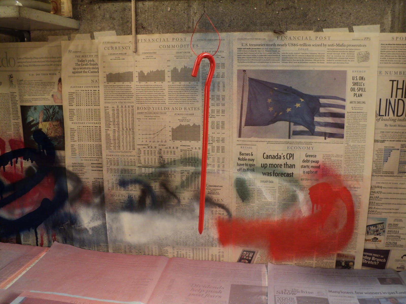
It's a slightly rusty, slightly bent steel tent peg with a blunt pointy end, obviously. What's not so obvious is what I see, near-instantaneously, when I look at it. What I see is this.


Here's how you get from one to the other. First, you hammer out the bentness on the back of the vise with a suitable hammer.


Then you clean the thing up by wire-brushing and steel-wooling and what-have-you.


Then you improve the pointy end a bit on the grinder, and touch up little dings and rough spots with a file.

You rig a way to suspend the thing for spray painting, clean it with lacquer thinner, and give it a coat of primer.


Then two coats of enamel.


And you have a tent peg that you're unlikely to leave behind at the campsite because you lost sight of it on the ground.

 # # #


 # # #

Saturday, February 23, 2013

Frying Pan Handle Revisited


This frying pan handle couldn't take the heat.


The back story to this is here. I still like the method I used to construct that handle, but it's evidently not suited for application to a frying pan handle; the wood/metal interface is too compact, so the wood is constantly getting charred. The outcome pictured above was inevitable.

I'm going to salvage that wooden handle, but I'll reconstruct it in a different manner. I'll do it in much the same fashion as I made this saucepan handle. The saucepan handle's construction is far superior because the wood/metal interface is relatively large -- more heat will go into the handle, away from the very end of the handle where it attaches to the frying pan. Here's a view of the components I'll be putting together.


The machined brass hose fitting is for 1/2" I.D. hose; the threaded rod is 1/2"-13 x 3" long. I don't have anything suitable on hand to make a ferrule from, so I'll use that 22mm hose clamp for a 'ferrule'. It won't be pretty, but it will do the job.

The hose fitting's bore is just shy of 1/2", so I'll run a tap through it to produce a vestigial female thread for the threaded rod. Here's a view of that operation just completed.


So now, I have the makings of a substantial, heat-sinking wood/metal interface, like so.


Next up is to bore the handle to accept the threaded rod and hose fitting assembly. There'll be four steps to that:

1) Centre drill to establish an initial, shallow pilot hole.

2) Drill a 3/16" pilot hole for the 5/8" spade bit that will bore the clearance for the hose fitting's barbed shank.

3) Drill 5/8" deep enough for the hose fitting.

4) Drill 1/2" deep enough for the threaded rod.

Here's the first step done.


That, and the follow-up 3/16" pilot hole was easy. For the 5/8" bore, I put a hose clamp on the work for reinforcement. Here's the 5/8" bore completed.


And here's the 1/2" bore completed.


And it all fits together.


Now I just have to clean everything, mix up a batch of J-B Weld epoxy and do the final, epoxy-bedded assembly.

- - -

Whoops!

As I was squeezing together the epoxy-slathered components in the vise, I was a little too quick and forceful, and I got a demonstration of hydraulic force at work, like so.


The wood cracked open and left me with a streak of squeeze-out where it wasn't supposed to occur. Fortunately, no real harm has been done there. I'll trim off that squeeze-out, and the flaw will be all but imperceptible. The crack is sealed against water incursion, and it's not extensive enough to be a structural defect.

What I should have done there as I was squeezing the handle parts together was do it very slowly, so the excess epoxy could all escape past the hose fitting in its own sweet time. J-B Weld mixes up into a very thick paste. I tried to rush the stuff, and it won't be rushed. Anyway, lesson learned. (For what it's worth, following is a close-up of the crack after trimming and sanding.)


- - -

A Ferrule

The saucepan handle has been serving as the frying pan's handle for several months now, and it's holding up fine. That handle has a true, encircling ferrule at its end where it attaches to the pan, and it occurs to me that that ferrule may be a key component -- it acts as a 'front line' heat dissipator for the wood. This handle is past the point where I could fit it with a ferrule in exactly the same way, but I can fake it with a split ring of copper pipe; it should at least be better than nothing.

- - -

Here's what I came up with.


That's a 3/4" length of 3/4" thin-walled (Type M) copper pipe. That 22mm hose clamp just manages full worm engagement over the final diameter.

I'll do a final assembly with a smear of J-B Weld under the copper 'ferrule', and I should have a handle that can take the heat. We'll see.

- - -

A Fresh Coat of Tung Oil -- MONDAY, FEBRUARY 25, 2013

Yesterday, I gave the wood a fresh coat of tung oil. I quite like the results I get from tung oil. Here's a view of the handle to date.


The photograph scarcely does the handle justice. The oil finish has a soft clarity to it that enhances the delicate figuring of the hardwood grain beneath. What the photograph can't show is the feel of the thing -- it's smooth but not slippery -- it's exquisite. As frying pan handles go, this is as pretty as they get.

Come the weekend, I'll re-install this handle on the frying pan, and commence observing how well and how long it stands up to its task.

- - -

Finally -- SUNDAY, MARCH 10, 2013


There it is re-installed and ready to go. We'll see if this reconstructed handle can take the heat.

Hose fitting threads are a pretty loose fit, so I wrapped eight turns of Teflon tape around the male thread, with the tape overlapping the end of the fitting so it would double as a gasket at the end of the fitting. The head of the hose clamp gave me a nice purchase-point for tightening the thing with Channellocks, without marring the handle at all.

The radial position of the hose clamp's head just happened to turn out as I wanted it -- the head facing down so it's pretty much out of sight. Had it not turned out that way, I could easily have made it so by adjusting the fastening of the female fitting.

That downward sloping attachment of the handle looks a bit odd, but on the stove it's not at all a problem. If anything, it's actually a bit of a safety improvement on the orthodox configuration -- the handle isn't sticking up where it's easily struck inadvertently.

- - -

Update -- FRIDAY, DECEMBER 19, 2014

The revised handle described above has lasted the better part of two years now, but it's looking a bit shabby.


So, I've made a new, more substantial one.


This time, I knew to provide a vent hole for the J-B Weld epoxy to escape from as I pressed the handle's components together. A tiny hole is all that's needed. I used a No. 60 (0.040") drill. After sanding and finishing the handle, the only evidence of the vent hole is a tiny, grey dot, like so.


I've given the handle a single coat of tung oil for a finish. The larger diameter of this handle (1 3/32") feels much better in the hand than the old, 7/8" diameter handle did. We'll see how it holds up.

# # #


# # #