Wednesday, June 1, 2011

A Bubble Level

I've had this little bubble level sitting in a drawer for years. I must have gotten it from an old colour laser printer that was being scrapped. I've finally thought of a use for it, but I'll want it to have a round base. 'Time to remove it from that steel rectangle and make it a proper base.

A 7/16" plate washer will serve for a base.

The screws are M2x6mm, and I don't have an M2 threading tap. I'll see if I can fake it with a bit of interference fit trickery and CA adhesive.

A proper machinist might sneer at some of my methods, but I find masking tape to be invaluable as a layout aid. Here's the washer covered in masking tape with the three hole locations transferred to it with a sharp pencil.

My close-up vision is not what it used to be, and a layout done on masking tape is helpful to me because of the tape's 'impressibility'. With points spotted on masking tape, I can make small impressions in the tape at those points with an awl point while viewing the work under an illuminated magnifier. Those impressions in the tape then give me a tactile way to confirm that I'm locating the point of a centre punch correctly.

Here's the washer having just been drilled with quite remarkable accuracy.

Those holes were drilled with a No. 49 drill. I'll explain how I arrived at that size of drill.

Miking the screws gave me their diameter as 0.075". A No. 49 drill is 0.073" diameter. There's my interference fit. I'll be forcefully installing the screws in holes that are 0.002" undersize.

- - -

And here's the completed level.

That more-or-less worked. I would like to have had slightly longer screws -- one of the three screws stripped instead of gripping; the screws only had a couple of threads worth of engagement. The other two went in ok. I applied CA adhesive to the ends of the screws from the underside of the washer so it could wick in around the screws.

I think I can call that a success. For what little is being asked of those screws, my interference fit w/CA adhesive added is quite adequate. Now I can get my wife's miniature birdbath installed with its bowl level. (I did mention early on that I had thought of a use for this thing. Here it is. Scroll way down.)

# # #


# # #

Sunday, May 29, 2011

Fiskars Pruning Stik Jam-Proofing

If you own one of these sets of pruning shears, you may have noticed that they have a tendency to jam at the ball-shaped pull at the handle's end. (Fiskars may have solved this since my set of shears were made, but it's an annoying problem on my old shears.)

The shears are of excellent quality, but the ball-ended pull at the end of the handle leaves a bit to be desired. Here's a shot of it at rest in its normal at-rest position.

Note the gap between the 'ball' and the handle tube's end-cap. That gap is a good thing to have there.

Now, here's a shot of the same thing after the shears have been set down on the ball-shaped pull's end a few times.

The gap is gone. Where did it go? It went into jamming the pull's shank into its receiver so tightly that you'll only get it back out by clamping a set of Channellocks on it and twisting it. (Hence the jaw marks you can see on the 'ball'.)

In the following shot is the entire pull after having been forcibly extracted.

Note the tapered shank. A tapered shank in a tapered bore will jam there; it's a law of nature. It's the reason that lathe centres are made the way they are, with tapered shanks on them. What were they thinking?

Anyway, there's a quick, effective and dirt-cheap way to solve this.

Put a small ty-wrap around the pull's shank. The ty-wrap will prevent the pull's tapered shank from seating in its tapered bore. If the shank can't seat, it can't jam.

The tiny bit of pull extension added by the ty-wrap has a negligible effect on the at-rest position of the shears' jaws.

# # #


# # #

Serpentine Belt Replacement

[I'll be dealing with the serpentine belt on a 1999 Ford Ranger, 3.0 litre V6 w/o A/C here, but most of what follows is applicable to any vehicle's belt.]

- - -

Serpentine belts are a brilliant piece of engineering -- I consider them a huge advance over the old V-belts. But they do present a couple of small challenges if you're new to the job of replacing one.

The first thing you need to get is a wrench that will enable you to crank the tension idler pulley away from the installed belt. Tension idler pulleys are strongly sprung, and an ordinary combination wrench is unlikely to be long enough. If the hex in the centre of the pulley has sufficient clearance in front of it, a breaker bar with a shallow socket will work fine. Odds are, though, that the pulley will be in cramped quarters, and you'll need something with a much lower profile to get on the pulley's hex.

Purpose-made wrenches can be had from an auto supply. I solved the problem for my Ranger by modifying an inexpensive 15mm combination wrench as in the following photograph.

I heated the wrench near its open end to about dull red and gave it a 90° twist. Now I can clamp a set of vise-grips on it for extra leverage while the box end is on the tension idler's hex. It works quite nicely. (An ordinary propane torch burning the hot fuel is entirely adequate for heating a wrench for this purpose.)

Once you have a suitable wrench, you're ready to go, but a word of caution is in order first.

If you're a gifted natural mechanic who can just intuit how things go together, go right ahead and remove and replace your belt. If your abilities are a bit shy of the 'gifted' characterization, as are mine, don't even think about removing the old belt until you have an accurate sketch of its path on hand. You'd be surprised at how mind-boggling a serpentine belt can be when you're confronted by a barren array of pulleys, a new belt in hand and nothing to guide you.

The packaging sleeve of a new belt will likely have what you need already printed on it, like so.

Those are excellent drawings, but play it safe and take a moment to confirm that a drawing agrees with what you see on your vehicle. If you don't have a belt-path drawing for your vehicle, make one. It needn't be draughtsman-quality, just clear and unambiguous.

With your wrench in place and the tension idler cranked you can slip the old belt off the idler, then off the alternator pulley and remove it from the pulley array entirely. The job is complicated a bit on the Ranger by the presence of a huge cooling fan that the belt must be coaxed over frontward for complete removal.

In any event, you'll arrive at a point where you're at an obvious end/beginning, like this.

On the Ranger, it's the power steering pump's pulley. Any pulley array will have an analogous place in it. That's where you start from with the new belt. With that starting point in mind and your sketch at hand, you can't go wrong.

# # #


# # #

Whirlpool Washer Won't Drain -- Lid Switch Trouble

If your washer won't drain after agitating, the reason it won't drain is likely that it can't commence spinning. (The washer's drain function is linked to its spin function.[1])

The reason the washer can't spin is likely that its lid switch isn't making. The lid switch is a safety interlock feature that precludes the possibility of one sticking one's arm into a spinning tub and being injured by it.

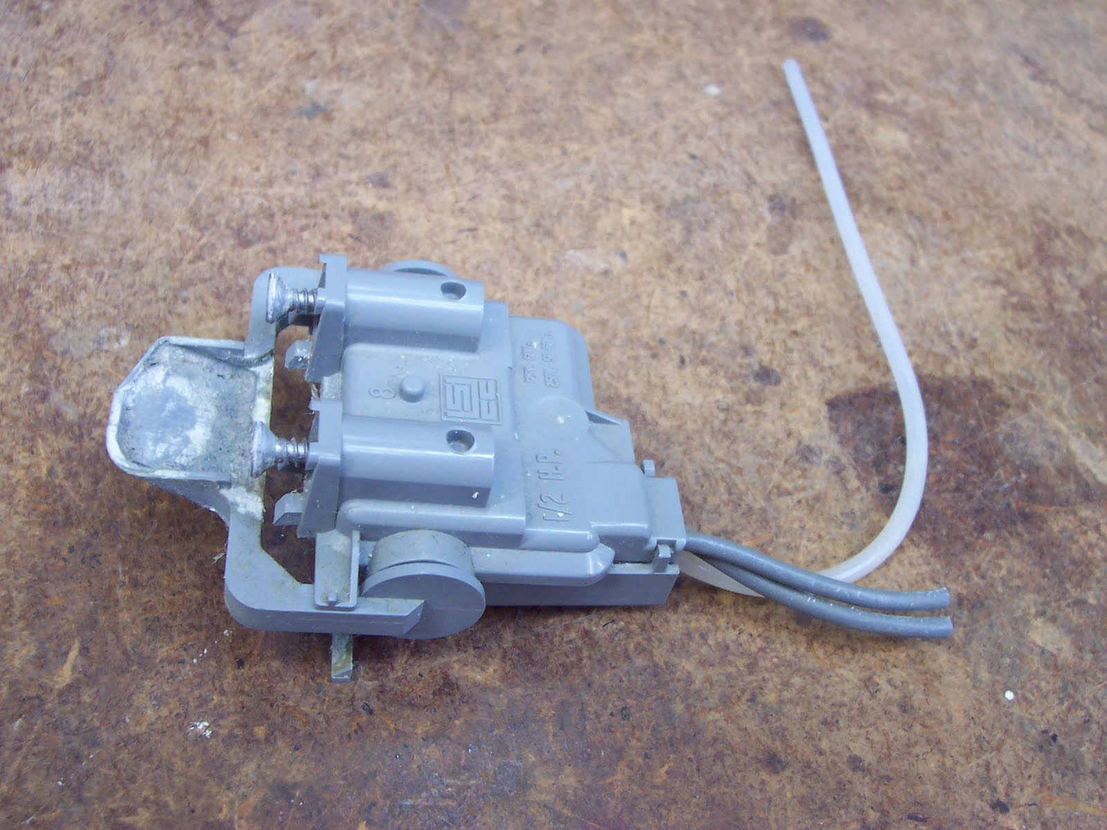
The lid switch on our Whirlpool Ultimate Care II washer gave me exactly that problem recently. The switch resides at the right side of the tub lid opening, where a projection on the underside of the lid actuates it. While investigating it, I noticed that if I pushed its lever further than normal, the switch would make, and the washer would commence spinning/draining. That little experiment ended when the body of the switch broke half apart. I unscrewed it and clipped its wires and removed it. Here it is.

It's quite an elaborate looking piece of gear for an SPST[2] interlock switch. That length of tubing stretching away from it mystifies me. I have no idea why that's there. I can see no conceivable purpose that it serves.

I took it apart completely, and a spring and a mangled contact flew out of it.

I managed to straighten the contact and get it all back together. In the following photo, you can see how it operates. (It's upside down in the photo.)

When the external lever is pressed by the projection on the washer's lid, an internal lever rocks against that taut extension spring in the back, and that ultimately causes the moveable switch contact to snap over and close the circuit.

I could conceivably have burnished the contacts and sealed the housing back together to repair it, but I didn't care to take the chance that it might still give me trouble.

I went to an appliance parts dealer near where I work and asked what they want for a new one. I was thinking that a replacement would likely eat a twenty dollar bill, and I was ok with that. The counter guy quoted me $51.08!

For $51.08 I can post a notice in the laundry room that says, "DON'T REACH INTO THE TUB WHEN IT'S SPINNING!", and splice the switch's wires permanently. Here's my method for making an ultra-reliable wiring connection for a hostile environment.

First, strip and twist together the wire ends as you would for a regular wire nut connection. (It looks like 18AWG stranded wire they used here.)

Solder the splice with 60/40 flux-core electronics solder, and trim the length if need be to fit a wire nut correctly.

Install a wire nut, and back fill it with an RTV silicone gasket maker like Permatex Ultra Grey.

Leave it to cure undisturbed.


- - -

Once it's cured, I'll tuck it away securely and there's an end to lid switch trouble on this washer. And if the 'safety' authorities are genuinely concerned for peoples' safety, they might suggest to the likes of Whirlpool that they cease over-engineering a simple function like an interlock switch, and make it affordable to replace. Meanwhile, I'll keep working around the idiotic 'system' and hang onto as many after-tax dollars as possible.


- - -

SATURDAY, JULY 16, 2011

ADDENDUM

I left something out.

To finish off the wire splice pictured above, cinch a miniature ty-wrap around the wires just above the wire nut. Any forces attempting to separate the wires will be taken by the ty-wrap, and not transmitted to where the wires are immersed in sealant.


- - -

Notes:

[1] This is an exquisite example of how machinery failure symptoms can be utterly baffling and misleading, for want of a little information about how a thing works.

As I said, the washer's drain function is linked to its spin function. If you're unaware that the spin function is interlocked, and that interlock switches tend not to age gracefully, you can go off on all manner of tangents trying to figure out what's wrong. The documentation supplied with the appliance is unlikely to be helpful, and much, if not most, of what you find on the internet is gibberish.

[2] 'SPST' = 'Single Pole Single Throw' -- a bit of shot-form switch configuration terminology. There are endless variations of switching configurations. SPST is the simplest; a single set of contacts is either open or closed, on or off.

# # #


# # #

Monday, May 23, 2011

Pruning Shears Pivot Replacement

My wife was using these shears out in the garden when they came apart on her. The pivot screw and nut promptly vapourized, and drifted off to whatever dimension or parallel universe such things go to when they vanish. A replacement pivot is in order.

The pivot bore is 8mm diameter, with a 'squaring' at one side of one shear. I imagine the idea of the squaring was to hold the pivot screw from rotating when the nut was installed and/or adjusted -- not an essential feature. I'll file[1] away the squaring so there'll be a clear 8mm bore all the way through.

An obvious way to repair this would be to install an M8 screw and nut to act as a pivot, but that's a poor practice. It makes for a pivot with very little bearing surface -- only the crests of the screw's threads. It would be prone to wear quickly, and the relatively large M8 screw head and nut would look awful. A much better pivot will obtain from an 8mm diameter rod bored through for an M4 screw.

- - -

Here's the rod in the lathe having just been squared off and bored to sufficient depth.

(By the way, a 5/32" drill is as close to 4mm as 'damn' is to swearing; 5/32" = 3.97mm.)

It would be nice now if I could just part off the needed length of bored rod, but I haven't yet acquired a parting cutter for this lathe. I'll have to saw off a slightly overlong piece and trim it down to correct length; i.e. just a bit less than the total thickness of the shears' two halves at the pivot point.

- - -

Here are all the components ready for assembly.

A ny-lock nut is ideal here; it will stay put once installed and adjusted. The screw was a standard 25mm long one that I ground down to exact length for this application. The flat washers are oversize No. 6. They just fit over the threaded portion of that M4 screw. I had to bore one out just a little for it to fit the unthreaded shank. The god of even numbers must have smiling on me while I was trimming the rod to length by trial-and-error; its finished length turned out to be exactly 10.0 mm.

And here are the shears sharpened, oiled and back together ready for use.

Quite a neat job, if I do say so myself.

- - -

[1] The steel at the pivot point is quite hard, but not too hard to file with chainsaw files. I could have drilled it through on the drill press, but it would have been an awkward thing to secure for drilling safely, and would probably have dulled a drill badly.

Had I thought of them, I had just the little hand grinder stones I needed sitting in a drawer.

They're chainsaw sharpening stones. I should get all the sizes of them, and keep them where I can see them. I can see this style of stone being quite versatile.

# # #


# # #

Thursday, May 19, 2011

A Stake for a Miniature Bird Bath

My wife found this miniature bird bath somewhere or other. It's quite an elegant little garden ornament, but it has no stake to stand it up by. So, unsurprisingly, it's on my workbench waiting to be attended to.

At the centre of its underside there's a round boss with a poorly threaded 10-32 hole in it. I applied a plug tap and a bottoming tap to it, and now it's properly threaded for the full 9/16" depth of the hole.

A three foot length of 5/16" diameter plated steel rod that I have on hand will make a stake for it. I just have to make one end pointy for going into the ground, and fit the top end with a 10-32 stud. It'll make for a pleasant little machine shop project.

- - -

And no sooner had I started the machining of the pointy end of the stake than I ran into a little complication. When you have a long piece of slender rod chucked in the lathe, the end of the rod that's hanging out the back of the lathe's spindle is free to flail about quite wildly. That action needed taming, so I came up with this -- the rag bearing. Details are at the link just provided, but here's how it looks.

I was pleasantly surprised by how well it worked and how easy it was to set up. It let me peacefully get on with machining the pointy end, and I soon had this.

Now it's time for the 10-32 threaded end. There are a number of ways such a thing can be done. An obvious one would be to turn down the rod end's diameter and thread that directly, but that struck me as bearing too close a resemblance to work. There's an easier way that will give an excellent result.

I'm quite partial to interference fits and the use of pins in permanent mechanical assemblies, so I'll use those methods here.

First, I cut the head off a 10-32 screw to obtain a 1 1/8" long 10-32 stud. Miking the screw threads' major diameter showed me 0.182". A No. 15 drill is 0.180" diameter -- there's my interference fit. I squared off the top end of the rod and bored a N0. 15 size hole in it to a depth of 9/16". Here are the rod end and the stud ready for assembly.

I chamfered one end of the stud a bit to make it easier to get it started into the hole. The two nuts are jammed together there so I can hammer the stud without damaging its end. Just prior to assembly, I coated the stud's threads with CA adhesive, and then hammered it in. And just for good measure, I added a 1/16" diameter roll pin to secure the stud for good. Here it is assembled and with the roll pin in place.

The roll pin was a cheap one from an assortment from Princess Auto. I haven't been too impressed with the dimension tolerances of their small diameter roll pins, and this one went in a little more easily than I would have liked. I flooded it CA adhesive to secure it.

There's a little embellishment you can do on a roll pin installation to make the pin ends all but disappear, and I went ahead and did it to this one. Here's how it looks.

That's a length of 0.040" wire inserted and glued with CA adhesive. Once I've painted this, there'll be no way that water can get into the pin's centre.

So, the thing is ready for its flat black paint job. As luck would have it, I recently built a spray-painting lathe for painting just this sort of thing. I just have to make up suitable adapters for this rod to go onto the lathe.

- - -

And here we are. Following are two shots of the rod in the spray-painting lathe.


This will be a breeze to paint. I'll just have to touch up the very tip of the pointy end where it will have been masked by the tailstock cup centre that I made by centre-drilling the head of a 1/4" carriage bolt.

- - -

Here's a shot of the finished interface.

I'll do a final assembly of this and the decorative elements on top with blue threadlocker, and it'll be ready for installation.

- - -

And here it is in its new home.

I took this shot after it had already been outside for a week or two, and the thing has rusted a bit. I think I'll just call that 'rustic charm', and leave it at that. I had a picture of it when I had just installed it, but I was embarrassed by it because the bowl wasn't level, so I deleted the picture. In the meantime, I rigged this little bubble level to help me install it properly. I just got that done today, so that's why you see a photograph of a 'new' birdbath with a level, but rusty, bowl.

- - -

SUNDAY, FEBRUARY 26, 2012

Addendum -- A Paint Job

By the end of the summer, my 'rustic charm' attitude had worn a bit thin. The factory's black finish really was worthless -- the birdbath acquired many splotches of orange surface rust that looked awful. A proper paint job was in order.

Spray painting small items is often a breeze; each coat takes about as long as it takes to get the can of paint well shaken. The challenge, though, can be to contrive a way to hold and manipulate an item while you paint it.

This birdbath lends itself to being rigged for painting relatively easily, because each of its three components has a threaded hole in it. The two flat head screws can be supported by a small block of wood with shallow holes drilled in it. Here's a view of the screws, and the two ornamental bits after painting, still mounted as they were for painting.

Those support 'stalks' are 3/8" diameter dowel, with lengths of M5 screw fixed in holes drilled in the ends of the dowels. The items pictured have received a coat of grey primer, and two coats of flat black enamel. They can go hide out in a safe place now for the paint to harden.

The birdbath's bowl has a 10-32 threaded hole in its bottom for a similar rig, but I'll have to come up with a stronger stalk construction. The bowl is much heavier than the ornamental pieces. I'll make something similar to the steel stake I made earlier.

- - -

And here we are.

That's a 6 1/2" length of 12mm diameter steel rod that I had on hand, with a length of 10-32 screw force-fitted into its end. Now I have a way to handle the bowl for painting.

I need to stock up on little Dremel wire brush wheels before I can proceed with this. What I'd like to have is a sand blast cabinet and an air compressor the size of a Jeep, but I don't have those things, so wire brushing will have to do. Here's a view of the inside of the bowl. You can see where I went at it a bit with a Dremel wire wheel.

That 'orange' rust is very light and comes away easily, it's just that there are countless little crevices to attend to. I'll photograph this again when it's ready for painting.

- - -

SATURDAY, APRIL 7, 2012

Sandblasting

The rusty bowl got me thinking about acquiring a sandblaster. I wasn't all that keen on the idea, because my air compressor is barely adequate to power one. Then Princess Auto came up with a little 'spot' sandblaster for $12.99, and I figured that might be worth a gamble. It worked out reasonably well; the story of it is here.

- - -


And here's the cleaned up bowl just freshly primed.

I'll have it fully painted today, and it can harden for a week or two. Then all the components will be ready for reassembly and installation.

- - -

SUNDAY, MAY 13, 2012

All Done and Back in the Garden


Much better. It no longer has that 'post-apocalyptic' look about it.

# # #


# # #

Sunday, May 15, 2011

Rag Bearing

If you need to do a machining operation at one end of a long piece of small diameter rod in the lathe, you're going to run into a little problem with the end of the rod that's hanging out the back of the lathe's spindle.

- - -

I needed to bore a hole in one end of a three foot length of 5/16" diameter steel rod recently, and when I chucked it and started up the lathe, the free end of the rod wanted to flail about something awful. Here's what I came up with to deal with it so I could proceed with the task at hand.

I call it a 'rag bearing' because that's exactly what it is. There are bronze bearings, there are ball bearings, there are roller bearings and there is this -- the rag bearing. I could scarcely get over how well it worked, and how easy it was to set up. Here's a closer view of it.


That's a square flannel rag folded over a few times, then folded in half and clamped in place on a plank. The plank is clamped to my drill press' table, which provides the bearing with an elevation adjustment. The rag bearing's fit is not snug -- it's actually quite loose. The bearing only needs to contain the rod end sufficiently that great oscillations can't get under way. With the rod end tamed this way, you can work away at the business end of the rod where it emerges from the chuck at your leisure; all that's happening at the free end of the rod is that it's getting a nice buffing.

# # #


# # #