Saturday, January 14, 2023

The Passing of Tom Gaspick

Tom Gaspick sadly passed away today in the early AM of January 14th after a short battle with Cancer. 

He will be missed and remembered by all those who loved him and all those he touched with his writing. 

Details of his funeral service will be posted here when available. 

Sunday, July 11, 2021

A Toy Model T Tank Truck

From a plan in the "GREAT BOOK OF WOODEN TOYS" by Norm Marshall and Bill Jones, published by Fox Chapel Publishing Company, Inc.


Some notes on the toy and the book:

  • A purist might object to my use of wood screws to attach/reinforce the fenders. The plan calls for sanded-flush dowels to do that. I'm not a purist, and sanding dowels flush is a pain in the neck. Aesthetically, I have no problem with the odd metal fastener on a wooden toy. Needless to say, any such fastener must be absolutely secure.
  • Norm Marshall was a brilliant designer -- all of the projects in the book are exquisite. The workmanship evidenced in the photographs is sublime.
  • That said, I take exception to the book's subtitle -- "More Than 50 Easy-to-Build Projects". Hmmm. I suppose that 'Difficult-to-Build' would not advance book sales, but it would be closer to the truth. A reasonably good execution of the toys' plans demands a well equipped workshop, and a pretty good mastery of the machinery and tools therein. A marginally equipped beginning woodworker is likely to be frustrated. Many aspects of the builds are technically challenging.
  • The text is often light on specifics. Something like the following doesn't cut it for me: "Lay out the fenders (G) on a piece of stock; then use a bandsaw or scroll saw to cut them out." The pictured fenders are flawless. They were not likely produced on a bandsaw -- a typical bandsaw blade is a rough-cutting beast. I'd like to know what machine, with what manner of blade, the author used to get such a perfect outcome.
  • The drafting leaves a bit to be desired in some cases.
Anyway, there are my quibbles with the book. By all means acquire the book and proceed to produce some delightful toys but be warned, the toys are not `easy-to-build`.

# # #


# # #

Friday, June 25, 2021

A Broken Caster Mount

 I built this little workshop truck years ago. The top is about 18" x 24".


It was never meant to be an outdoor item, but it's been outside for the past couple of years, and the exposure has taken its toll on the paint job. The exposure has also resulted in the failure of a particleboard caster mounting disc.


The fracture lined back up nicely. Gorilla Glue and a couple of c-clamps will have the truck back in business tomorrow.


# # #

FEEDBACK

# # # 

Tuesday, June 22, 2021

Mastercraft 9" Band Saw (055-6748-6) -- Rear Blade Support Bearing Failure

The rear blade support bearings lead a hard life, and both bearings on my machine have lost their outer seals. The lower bearing, showered as it is with sawdust, has all but seized up.

The saw has an upper rear blade support bearing (two views).


And a lower rear blade support bearing (two views).


Replacement Bearings

The bearings are No. 606RS -- 6mm bore x 17mm O.D. x 6mm width, sealed both sides. Replacements are readily available from Amazon.

Lower Bearing Replacement
  • Release blade tension and get the blade out of the way.
  • With a 4mm hex key, loosen off the setscrew securing the bearing's mounting post. (A hole in the front of the saw's frame gives access to the setscrew's head.) Remove the post/bearing assembly.
  • With a 4mm hex key, remove the M5 x 16mm screw fastening the bearing to the post. Mind the flat washers on either side of the bearing.
  • Replace the bearing. Reinstall the post/bearing assembly loosely.
  • Reinstall the blade and spin it manually to reestablish blade tracking. The back of the blade should be just touching the upper rear blade support bearing.
  • Adjust the lower post/bearing assembly so that the blade is just touching the lower rear blade support bearing.
  • Lock the post/bearing assembly in place with the setscrew.
Upper Bearing Replacement

The upper bearing's mounting post is different from that of the lower bearing -- it's not readily removable from the saw's frame with its bearing attached. Proceed as follows.
  • Have the blade tensioned and running true. The back of the blade should be just touching the lower rear blade support bearing.
  • Swing open the black shield concealing the upper blade guide.
  • With a 4mm hex key, loosen off the screw fastening the bearing's mounting post to the saw's frame.
  • Slide the post/bearing assembly back as far as it will go. The bearing is now fully accessible for removal.
  • With a 4mm hex key, remove the M5 x 16mm screw fastening the bearing to the post. Mind the flat washers on either side of the bearing.
  • Replace the bearing.
  • Move the bearing's mounting post forward so the bearing just contacts the rear of the blade.
  • Lock the post/bearing/assembly in place with the screw.
Note:

The saw's Instruction Manual calls for a 0.002" gap between the bearings and the rear of the blade. Such adjustment strikes me as difficult, pointless and needless. I simply adjust the bearings so that they are in contact with the rear of the blade.

# # #


# # #

Friday, May 21, 2021

A Tecumseh TVS 90 Catastrophic Failure

 The mower started up fine, then it started to make a clattering noise, then WHACK! A piece of the connecting rod came flying out the right side of the crankcase, leaving a gaping hole.


Here's a view of the connecting rod big end piece that emerged from the engine.


For want of anything better to do, I may open up the engine for a look inside at the damage. We'll see.

* * *

Well, I didn't open up the engine, but I did remove the cylinder head. I extracted the piston, and retrieved another piece of the connecting rod's big end. Here's what I got.


The failure is inexplicable. I'm careful about checking engine oil, and would never let an engine run out of oil. Anyway, that's the end of that engine.

# # #

FEEDBACK

# # #


Friday, February 5, 2021

A Coffee Mill

Loosely based on a design from the book "Woodworking Projects For the Home Workshop" by Rosario Capotosto, here's a view of my completed coffee mill[1].


The grinder is Busy Bee's No. B3962, antique style side crank coffee grinder. Busy Bee also offers a top crank model for less money, but I thought that the side crank version is the superior design.

Dimensions

The base is 6 5/8" square with 3/4" corner radii. The box is 5 1/4" square with a 4 3/8" height. Overall height with the grinder attached is 12 3/16".

Material

I was determined to make the thing out of whatever I had on hand, so aesthetics took a back seat to the limitations of reality.

The base with its radiused corners is 3/4" firply. The firply edges are veneered with birch hot-melt edge veneer (the only item I had no choice but to buy). The firply base contrasts mightily with the pine box and the birch edge veneer, but as I said, aesthetics took a back seat.

The box is made of 1/2" thick pine, as is the drawer front. I had to thickness plane 3/4" material to get the 1/2" material. The drawer's body is made from 1/4" thick poplar plywood (subflooring plywood).

Fasteners

Supplied with the grinder are two 8-32 x 1 1/2" black pan head screws and two 5/16" A/F hex nuts. I added two No. 8 SAE flat washers, and two No. 8 split lockwashers for under the hex nuts. The screws' threads are slightly undersize from true No. 8 stud diameter for some reason. The hex nuts are undersize as well -- standard 8-32 hex nuts are 11/32" A/F.

The drawer front is fastened to the drawer sides with 3/4" finishing nails. 1/2" finishing nails are used throughout the remainder of the drawer's construction.

The base is fastened to the box from underneath with nine No. 6 x 1 1/4" flathead wood screws. Attaching the box to the base is a tricky operation.

The Drawer Pull

It's an antiquey, oddball item I had lying around. Most anything would suffice.

Finish

One application of tung oil.

Grinder Action

The mill works as advertised, producing quite a fine grind.


It took a lot of cranking to produce the little heap of ground coffee in the above photograph.

In Conclusion

It's a satisfying little woodworking project that delivers the expected result. Be warned that you'll have to enjoy turning a crank if you expect to grind a lot of coffee.

* * *

Note:

[1] The terms 'coffee mill' and 'coffee grinder' seem to be used interchangeably. I consider a coffee mill to be a complete unit with grinder and catch vessel; a coffee grinder to be the grinder mechanism only.

# # #

FEEDBACK

# # #


Friday, July 24, 2020

Windshield Washer Failure -- 2009 Hyundai Tucson


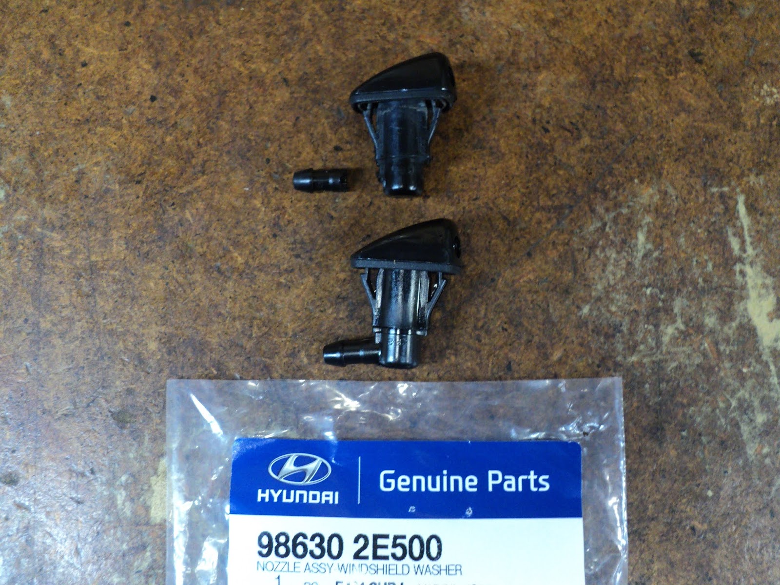
'Went to use the windshield washer the other day and nothing; the wipers did their thing, and I could hear the pump whirring, but there was no washer fluid emerging from the nozzles. A check under the hood revealed that the washer fluid hose was hanging loose on the driver's side. All the fluid that the pump was providing was coming out of the loose hose end. The failure was a snapped off hose nipple on the driver's side nozzle. Here's a view of the failed nozzle with its broken off nipple that I retrieved from the hose end, along with the new nozzle.


The nozzle's part number is 98630 2E500. (My local Hyundai dealer always asks for a VIN in order to look up a part.) Hyundai parts are not cheap; the new nozzle was $19.14 CDN + HST.

The nozzle is held in place by two claws -- one in front and one in back. The claw in front is easy enough to access to push on with a screwdriver and free. The claw in back calls for a tool that can reach in behind to pull the claw forward. A 90 degree mechanic's scribe like the one pictured below worked for me.


The new part just snaps into place in its opening in the hood. The hose goes on the nipple and you're away.

# # #


# # #

Sunday, December 8, 2019

A Murray ELECTRIC 20 Snow Thrower


A roadside find.


Overall from the outside, it looks to be in remarkably good condition. It's a 12A, 20 inch swath single stage machine.

Model No. is 620000X30NA
S/N 735492872S2C050C
D.O.M. 2002.10.14

- - -

Something looks and feels fishy about the 'On' trigger though. There appears to be a missing safety interlock key, and the trigger's action doesn't feel right.


And sure enough, plugging in the snow thrower and trying it results in nothing. 'Time to investigate how the mystery interlock operates.

- - -

It turns out that that hexagon at about the centre of the above photo has to be turned slightly in the CW direction to enable the switch lever. The machine does run with that detail attended to. So, now I know that the machine only needs a replacement key (P/N 583356) in order to be operable. The next question is, "What's the condition of the drive belt?"

If the belt is good, this may be a saleable machine. If belt replacement is called for, a new belt may be too much money. (Belt P/N is 760976MA.) We'll see. 'Time to get the belt cover off for a look see.

Belt Cover Removal

It's quite an array of fasteners that hold the belt cover in place.

  1. At the front there are five 10-24 x 1/2" hex washerhead bolts, 5/16" across flats (A/F) with 3/8" A/F prevailing torque hex nuts.
  2. At the bottom-front, there is one 10-24 x 1/2" hex washerhead bolt, 5/16" A/F with a 3/8" A/F prevailing torque hex nut.
  3. At the upper-rear there are two 1/4" x 3/4" hex washerhead threading screws, 3/8" A/F.
  4. At the lower-rear toward the front, there's a 1/4"-20 x 1/2" hex head screw, 7/16" A/F, with a flat washer. It's important that this 1/2" long screw be reinstalled at its correct location. A longer screw here might interfere with the drive belt.
  5. At the lower-rear toward the rear, there's a 1/4" x 3/4" hex washerhead threading screw, 3/8" A/F, with a flat washer.
And with those ten fasteners removed, one has access to the drive belt, like so.


And as it fortunately turns out, the belt is in fine condition, and all is in good order with its pulleys.

- - -

So, if I can obtain a safety interlock key, I'll have a saleable machine here.

# # #


# # #

Saturday, December 7, 2019

A Zippo Lighter Fluid Hack


If you're an incorrigible smoker, and you're buying your lighter fluid in 12 ounce or smaller containers, you're paying way too much. Here's a work-around that saves money.


Get yourself a Yankee gallon (3.780 ml) of Coleman camp fuel, and you'll have plenty of lighter fluid for way less[1] than you've been paying for the little bottles of Ronsonol or Zippo lighter fluid.

You will need a small Ronsonol bottle for the sake of its convenient cap/spout. The Ronsonol bottle pictured above is the 341 ml size. Its cap can be pried off with a suitable plain slot screwdriver. Then, with a suitable small funnel,[2] the Ronsonol bottle can be refilled from the big can of camp fuel. Snap the cap/spout back on the Ronsonol bottle and you're away.

- - -

Notes:

[1] I won't bore the reader with the math, but the camp fuel is less than half the price of the lighter fluid.

[2] The funnel pictured is an elderly Coleman No. 0, which I don't believe is available anymore. Try a dollar store or a hardware outlet for funnels.

# # #


# # #

Sunday, November 17, 2019

A Toro Power Curve 1800 Snow Thrower


Someone brought me an electric snow thrower to repair. It's a Toro model No. 38025, S/N 290008995 -- an 18" swath, 12 amp machine.

It's missing its final drive belt, and the toothed primary drive belt is looking a bit frayed. Here's a view of the left side of the unit, where the belts reside.


Final drive belt replacement looks like it should be a breeze. Primary drive belt replacement will involve removing a pulley.

- - -

Intermediate Pulley Removal


That 9/16" A/F (across flats) hex is the head of the intermediate pulley's spindle. It has a left-hand thread, so it's CW to remove it. Removing the spindle with its pulley gets you to here.


The toothed belt's Toro P/N is 73-0160. Belt width is 19mm. On close inspection, the belt appears to be in good condition, and needn't be replaced.

- - -

Final Drive Belt


It's Toro P/N 61-8802; a five-ribbed belt. The belt is a tight fit -- it takes a bit of doing to get it on its pulleys. You may want to unspring the tension idler to make installation a little easier. Belt tension seems excessive to me, but it is the correct belt.

Here's a view of the installed belt.


Left Side Cover

The cover was missing its three fastening screws, and an associated skid plate. I replaced the screws with No. 8 x 3/4" hex washerhead sheet metal screws, GC Electronics P/N 11-206-C. The machine will have to do without its left side skid plate, unless the owner can find what's become of it. Here's a view of the left side cover installed with its replacement screws


Discharge Chute

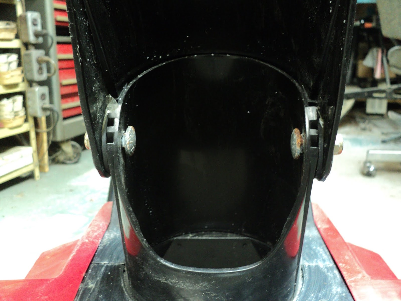
The upper deflector portion of the chute is loose on its pivots.


The 5/16" x 1" carriage bolts aren't seated in their square recesses, and the prevailing torque of the nyloc nuts is too great for the plastic material to resist. Trying to tighten the nyloc nuts only causes the bolts to turn. The bolts' shanks won't seat in the square recesses. The pivoting/tensioning scheme cannot work as designed.

I replaced the carriage bolts with 1" hex head bolts with 5/16" plate washers under the heads. That makes it possible to snug up the bolts so the deflector is properly tensioned.

In Conclusion

A worthwhile repair, I suppose, although the price of the replacement final drive belt struck me as outrageous -- $46.46 CDN + HST came to $52.50! A new replacement machine, same make and model, is $449.00 CDN + HST at the Home Depot, so repair cost here was within reason.

- - -

Missing Left Side Skid Plate Dealt With -- WEDNESDAY, NOVEMBER 20, 2019

That missing left side skid was bothering me, so I came up with a fix. Here's a view of the skid that's on the right side leading edge of the auger housing.


Note the two tabs that employ two right side cover screws to fasten the skid in place.

I could see no practicable way to fabricate a truly equivalent part.[1] So, I fabricated a skid with a different fastening scheme. Here's a view of what I came up with for the left side.


That's a 5" length of 1/8" x 1/2" steel flat, rolled to conform to the auger housing's profile. Three countersunk holes accept No. 5 x 1/2" flat head wood screws. It looks to me like a sound arrangement -- I'm quite pleased with it.

- - -

Addendum -- FRIDAY, NOVEMBER 29, 2019 -- Get The Idler Tension Spring Hooked On Right!

You want the idler tension spring to be securely hooked. Here's how it ought to look.


If the spring is hooked the other way around, the hooking won't be nearly as secure.

* * *

Note:

[1] "So why not just obtain an OEM replacement for the missing skid?", you may ask.

Too much aggravation and expense is why. Another trip out to the small engines place in Pickering, where they'd be unlikely to stock such an item. Then, if the part were available to be ordered, another trip out to Pickering to collect it, plus the cost of the part itself.

By fabricating a functionally equivalent part from material I had on hand, I bypassed all that and I now have a truly finished repair that I can return to the customer right now. An outcome well worth the effort of part fabrication.


# # #


# # #

Saturday, November 9, 2019

A Freakish Knife Failure


Found in the dishwasher after a wash cycle.


A supposedly high quality Cuisine de France chef's knife. It just up and broke in two -- quite mind boggling.

And it was one of my wife's favourites.

Anyway, there's no conceivable way of repairing that, that's for sure.

# # #


# # #

Tuesday, November 5, 2019

Honda HS621 Snow Thrower Oil Change


Changing the oil in a Honda HS621 snow thrower is a bit awkward owing to the placement of the drain plug and the filler neck. Here are a couple of items that make the job relatively easy.

First is a suitable drain pan. In Canadian Tire's kitchenwares section, I found a Lagostina cake pan that's 9" square by about 1 1/2" deep. It's perfectly suited to the task. The pan was on special so the price was reasonable. A dollar store might have something similar for even less money, though. Here's a view of the pan in position for draining the oil.


The drain plug's hex takes a 10mm socket wrench.

Second, you'll need a funnel with a 9" length of tubing for a neck extension. Here's what I cobbled together from what I had on hand.


That solves the difficulty of getting to the engine's oil filler neck.

Honda's oil recommendation is 5W30. Sump capacity is 600ml. With a full sump, oil should just be visible at the opening of the filler neck.

# # #


# # #

A No-Name 19" Push Lawnmower


A roadside find, in rough condition, possibly destined to be scrap metal.


It's also easily the ugliest lawnmower I've ever seen -- a dreadful colour scheme.

Anyway, the first order of business is to deal with the stuck starter. It won't recoil. The starter cord's handle is some sort of steel bracket.


- - -

Starter Working

The spring needed winding up. The cord is too short to be parked up on the handlebar as it ought to be, but it's long enough to work so I can test for spark.

- - -

Starter Update -- SUNDAY, NOVEMBER 24, 2019

I installed a new cord -- an 88" MTD/Atlas item from Canadian Tire. Canadian Tire P/N 60-7553-8. $5.99 CDN + HST. I had a salvaged grip on hand. The new arrangement works fine. The 88" cord length is adequate for parking the grip up on the handlebar.

- - -

Spark Plug

It's a Champion RJ19LM, which is correct for the engine. The plug is in reasonably good condition, but the gap is oversize. I set the gap to a snug 0.030". A spark test reveals that I do have spark.

Engine

Engine is a Tecumseh. As best I can make out the codes embossed on the front of the cowl, it's a TVS90 43368F SER 80686.

Compression Test

I got a reading of about 42 PSI. That's pretty lame. A well worn engine may exhibit 50 PSI, so this engine is past it. Just for the heckuvit, I'll see if I can get it to start and run.

- - -

Compression Test Update -- THURSDAY, NOVEMBER 7, 2019

I did get the engine to start and run. After running the engine for a brief while, I did another compression test. That test returned a reading of almost 60 PSI. I imagine that the piston rings got a good shakeup, and started to seat better in the cylinder's bore. 60 PSI is still not great compression, but in my experience, 60 PSI is viable compression -- the engine still has useful life in it.

- - -

Fuel Tank

The fuel tank lifts off two ways at the rear of the cowl. There's a spring-type hose clamp to be dealt with at the fuel line nipple.

The tank is all but empty. There doesn't appear to be water or sludge in it. The cap is cracked. The cap's gasket is ill-fitting, and falls out easily.

- - -

Fuel Tank Update -- SUNDAY, NOVEMBER 24, 2019

New red fuel tank cap. Tecumseh P/N 34210.

- - -

Air Cleaner

The air cleaner is mis-installed, and missing its cover. Two special 10-32 shoulder screws with 1/4" A/F (across flats) hex heads with No. 2 Phillips recesses fasten the air cleaner's body to the carburetor. There's a round gasket in the air cleaner's air horn where it contacts the carburetor. The gasket is inclined to stay in its groove and not come loose.

Cowl

At the front, two 10-24 x 1/2" hex washerhead screws with captive external tooth washers, 5/16" A/F.

At the rear, two 1/4"-20 hex washerhead screws, 3/8" A/F.

Governor/Throttle Control Plate On Top Of Carburetor


Note the positions of the adjustable features of the plate -- the throttle cable jacket's position and the plate's position.
  • Throttle cable. Loosen off the clamp (1/4" A/F hex) and unhook the cable.
  • Control plate. Two 10-24 x 1/2" hex washerhead screws with captive external tooth washers, 5/16" A/F.
  • Unhook the governor spring link.
Carburetor
  • Two 1/4"-28 x 7/8" hex head screws, 3/8" A/F with two 7/16" A/F KEPS nuts.
  • Note the position of the governor link in the throttle lever, and unhook the link.
  • Float Bowl Screw. 1/2" A/F hex.
The carburetor is a float bowl type, as simple a design as one will ever see. There are no adjustments aside from float level. There is no idle jetting. Pressing the primer bulb forces a visible squirt of fuel up and out of the main jet into the venturi.

- - -

Start Up Trial

'Put some fuel in it, gave it three primes and it started on the first pull. So, even with compression as low as 42 PSI, a four-stroke engine will start and run.

That doesn't save this lawnmower from the scrapyard, though. It's too ugly and too far gone to sell.

* * *

Oh, What The Hey -- SATURDAY, NOVEMBER 23, 2019

For want of anything better to do, I decided to go ahead and try to make a serviceable, saleable mower out of this piece of junk. That took a fair bit of doing. Here's what I've done.


Painting

I stripped the blue paint off the handlebars with paint remover. The handlebars, engine cowl and discharge chute all got painted gloss black. 'Looks much better.

Primer was Canadian Tire Armor Coat grey primer P/N 048-0621-0. Paint (two coats) was Canadian Tire Armor Coat gloss black enamel P/N 048-0314-2.

Deck Cracks Behind Rear Wheels

I cut two patch plates from 1 1/2" wide steel flat, and installed them with 1/8" hollow aluminum rivets, like so.


I also used the same 1 1/2" wide steel flat to fabricate two rectangular 'washers' for underneath the handlebar brackets.


The rear of the deck is now rigid as it ought to be.

Trailing Flap


The original flap was completely torn off. The pictured flap that I've installed is the same as that used on my own lawnmower. The parts breakdown in my user's manual gave me the part number -- MTD P/N 731-06953 -- so I was able to order one from the small engines place in Pickering.

For hinges, I used 1/2" All Round strapping. The hinges are anchored by two 10-24 aluminum threaded inserts, with 1/2" long hex socket head screws.

Air Cleaner Cover

The air cleaner cover was missing altogether. I had a salvaged one with a broken tab on it, so I made up for the broken tab with a 10-24 x 1" screw and another 10-24 aluminum threaded insert.


- - -

So there we are -- the mower is now a serviceable machine. I'll try peddling it on Kijiji come spring.

# # #


# # #

Monday, November 4, 2019

A YARD MACHINES by MTD 4.5HP/21" Snow Thrower


My son picked this up in working condition for $20.00 CDN. He's asked me to look it over before he tries flipping it for a profit.

It's an MTD MODEL 31A-150-500. MFG. CODE 21-074-4411

It's a single stage machine with a two-stroke engine. Fuel mix ratio is 50:1. There's a 120 VAC electric starter feature.

Engine is a Tecumseh:
  • ENGINE MODEL HSK845 8204D (H)
  • ENGINE FAMILY VTP139UB25RA
  • DISPLACEMENT 139
  • D.O.M. 7254G
Let's have a look-see and discover what sort of condition the machine is in.

A Motley Collection Of Auger Drive Cover Screws


The heads of the screws fastening the auger drive cover are all different. I'm almost afraid to discover what the screws' threads are. There's a cross-slot, a slot, a PoziDriv and a slotted hex head. there's one screw missing down below.

- - -

The screws are a mixed bag -- mostly threading (sheet metal) screws. I think they should all be 1/4"-20, so I chased the holes with a tap, and now I've got uniform 1/4"-20 screw locations at all five places. I'll install 1/2" long hex socket head screws, split lockwashers and flat washers at final reassembly.

The Auger Drive


The V-belt looks to be more-or-less ok. The tension idler feels lubricant-starved. I'll take that off and oil it as best I can.

Belt Tension Adjustment

The clutch control cable terminates in an extension spring that hooks onto the idler pulley bracket. There are three holes in the idler pulley bracket for the spring to hook into. The lowest hole affords the least belt tension. The two higher up holes afford progressively greater belt tension. Here's a view of that.


Note that the spring in the photo above is hooked into the lowest of the three holes, for least belt tension. That belt tension seemed marginal to me, so I hooked the spring into the middle hole.

Note also the second extension spring higher up. That's the idler pulley bracket return spring. The spring seen in the photo is not factory -- it's someone's kludged replacement. The return spring is not supposed to be hooked into a tension spring hole; it's supposed to hook onto that notch in the bracket that's just below the tensioning spring holes. I don't have a better replacement for the return spring, so I'll just have to leave that be.

The Top Cover

Remove nine threading screws to unfasten the top cover. Remove the fuel tank cap and the discharge chute's wingnut. The cover will be free to come away, though some forceful coaxing will be needed to get the cover past the exhaust pipe. Here's a view of the machine with the top cover off.


Note the electric starter motor directly below the muffler.

The Carburetor

The carburetor is a float bowl type, with no adjustments aside from float level. The float bowl is readily accessible from below, as can be seen in the following photograph.


I took the float bowl off for inspection. (A 1/2" wrench is needed.) There was some sediment in the bowl that I rinsed out. Float level looked satisfactory.

On reassembly, I ended up with a leak at the float bowl screw's gasket. The gasket is an ill-fitting thing. Reassembly and re-tightening solved the leak.

Carburetor Removal

Carburetor removal on this machine looks like a nasty bit of business -- not to be undertaken without a pressing reason for it.

It appears that in order to remove the carburetor, one must unfasten the dashboard to get it out of the way. Then, a ball-ended hex key might be needed to loosen off the carburetor's two fasteners, and I don't have any of those. Since this machine starts and runs satisfactorily, I'm going to leave well enough alone.

The Spark Plug

The spark plug is accessible via a hole in the dashboard. The spark plug in this machine's engine is an NGK BPMR7A, with a 3/4" hex and a 0.025" gap. The plug shows some evidence of oil fouling, but is in good condition. (The oil fouling may be from having run with too oily a fuel mix.)

And That's It

The machine starts and runs, and auger drive looks ok. It can go on Kijiji.

* * *

Update -- SATURDAY, MARCH 8, 2020

I never did put the machine up for sale. Instead, I let it sit unused all winter under the carport. I tried starting it today and it was no go -- the machine absolutely refused to start.

I dragged it into the workshop and checked for spark; that was ok. I uncovered the carburetor's intake and checked for priming. There was no evidence of priming spurts whatsoever. I upended the machine on the front of its auger housing and tried the primer bulb. Fuel emerged from around the float bowl's ring gasket. Bingo!

That explained a lot. With the float bowl's ring gasket leaking, pressing the primer bulb only blew air past the ring gasket; the float bowl wasn't being pressurized so that fuel would be forced up the main jet into the venturi. The priming function was rendered inoperative by the leaky float bowl ring gasket.

A replacement ring gasket solved the problem. A reminder that a small, normally invisible detail can disable an engine.

# # #

FEEDBACK

# # #

Saturday, October 26, 2019

A McCulloch Model MT2026 Corded String Trimmer


The trimmer hub is a disaster, and replacement parts are no longer available. There'll be no restoring this item to operability. I figure I'll take it to pieces just for the heckuvit. Maybe there'll be something of it that's worth salvaging.

The Hub


The hub's outer shell is a piece of wreckage. It appears that a repair to the torn out trimmer line exit holes has been attempted, to poor effect. The hub spring is an ill-fitting kludge -- not the original spring. I don't know what to make of the translucent sleeve over the trimmer line spool. How that arrangement could ever bump-feed trimmer line is beyond me.

The Business End


There's a steel rod bail holding the safety guard in place. (The bail rod is 4mm diameter.) With that bail pried loose and removed, the safety guard can be removed. The motor housing can then be opened up.

Opening Up The Motor Housing

The motor housing is fastened together by ten 4mm threading screws, No. 2 Phillips recess. One of the screws is concealed under the ID label. The two uppermost screws are 13mm long. The other eight screws are all 18 mm long.

Opening up the motor housing reveals two prominent features of the machine -- the handle length adjuster and the motor itself.

Handle Length Adjuster


There's a latch/detent affair that enables the handle shaft to have one of four different lengths. The length increments are just shy of one inch.

The latch and the detent lever are spring loaded by coil springs. (I'll salvage the springs.) It's a diabolical thing to reassemble if it springs apart on you, which it's very likely to do.

The Motor


The motor is quite robust looking. (It still works, by the way.) Motor rating is 120 VAC, 3.2 A, 10,000 rpm.

The motor mount bracket is fastened to the housing by two 4mm threading screws, No. 2 Phillips recess. That fan/hub on the output end of the motor appears to be press-fitted on. I can see no non-destructive way to remove it.

Motor Fan/Hub Removed

I bored into the centre of the plastic fan/hub so I could get a puller's nose to contact the motor's shaft. That got the fan/hub started coming off. From there, I was able to pry the fan/hub off the rest of the way. Here's a view of the motor out of its housing along with its detached fan/hub.


The motor's shaft is 8mm diameter, with splines that make for an interference fit with the fan/hub's bore. Shaft length is 15/16".

I rigged the motor for a no load current draw measurement, and a photo-tachometer reading. I got about 650 mA  at about 27,000 rpm. Evidently, the 3.2 A, 10,000 rpm rating represents full load values.

Anyway, I now have a very nice little universal motor that I can think of no possible use for.

The Handgrips


The lower handgrip is fastened by a single M6 x 52mm carriage bolt and wingnut. There's a flat washer under the wingnut.

The upper handgrip is held together by six 4mm threading screws, No. 2 Phillips recess. The two screws nearest the trigger are 13mm long; the remaining four screws are 18mm long

The Trigger Switch


The red trigger acts on a momentary slide switch. The slide switch is made by Defond. It's rated at 11 A, 125 VAC, 5.5 A, 250 VAC. Its terminals are 3/16" male spade terminals.

- - -

So there we have it -- the whole thing dismantled. Here's what all I salvaged:

  • Three compression springs.
  • Motor.
  • Slide switch.
  • An M6 x 52mm carriage bolt with wingnut and flat washer.
  • A 25 1/4" length of 7/8" diameter steel tubing.
# # #


# # #