Pages

Monday, July 28, 2014

A Spindle-Turning Lathe Restoration -- or -- Tom's Folly


It remains to be seen which.


I picked this up by way of Kijiji just recently.

It's a wood-turning lathe that's especially adapted to turning long, slender spindles. It has an extraordinary between-centres length of about 44", and it has a steady-rest. A steady-rest is standard equipment on metal-turning lathes, but it's a rare thing to see on a wood-turning lathe.

There's no manufacturer's name on it anywhere. It may be an off-shore item, but it doesn't have that slipshod off-shore look about it to my eye.

Anyway, I mean to restore this lathe to good-as-new or better condition. That should keep me out of trouble for quite some time.

- - -

A Tour Of The Machine As it Currently Is

The Motor Mount

This is quite a piece of fabrication. It slings the motor underneath the deck, with a lever affair up top that permits v-belt tension to be released for pulley step changes. Here's a view of the thing in its operating position.


And here it is in its tension released position.


I think there may be an easier way to mount the motor, so I won't be reusing this motor mount.

The Deck

The deck is about 18" x 64".

It's made of 1" thick planks, topped with 5/16" firply, edged with 1" x 2" then clad in 7/16" chipboard. It's soaking wet throughout from having been kept outside. Here's a view of it part-way through demolition.


The Legs

The legs are steel weldments made of heavy-gauge angle and flat. They're bolted to the deck by an assortment of 1/4" and 5/16" screws and nuts. The left side leg weldment has two broken welds where the angled bracing flats meet the uprights.


I don't have welding gear, so that will be a challenging problem to deal with. I'm thinking of bolting the brace-ends in place with fabricated steel corner braces. We'll see.

The Lathe Bed And Feet


The bed is two steel channels, 1 3/8" x 2 15/16" x 59 3/4" long, bolted to two identical foot/end castings.

The Headstock

The spindle has a 1" x 8tpi thread on its nose, and an MT2 taper. That's a pretty ordinary configuration for low-end lathes -- the same as on my Delta ShopMaster.


I was told that one of the bearings was running hot. I hope I can salvage the bearings, because they're a double-row, self-aligning type (SKF 1205) that'll likely be costly to replace. We'll see how that goes.

The Tailstock

I think it has an MT2 taper; I haven't tried to knock out the centre yet to find out for sure.


I gave it a shot of WD-40, and the
ram's motion is coming back with a very nice feel to it, so that's encouraging.

The Steady-Rest

It's a big, heavy item


Thankfully, there's not a single piece of it that's missing. I'm looking forward to trying it out.

- - -

So there's an overview of the machine. I'll provide much more detail as I attend to each item.

* * *

The Broken Leg-Brace Welds

As I mentioned earlier, I'm not equipped for welding, so I either have to get welding done for me, or find alternatives to welding when broken welds crop up. Finding alternatives is cheaper, and it affords me complete control of the job, so I'm inclined to find alternatives. Here's what I've come up with for a solution to the broken leg-brace welds.


I fabricated two corner braces from 1/8" thick by 1" wide steel flat, and installed them with 1/4"-20 screws and nuts. Their strength will be more than adequate once the legs are assembled to the deck.

Foot Pads

I thought I'd make the steel legs a little less intensely burdensome on whatever floor they may end up bearing down on, so I made four 3" diameter foot pads from 3/4" plywood with the aid of a fly cutter.


The fasteners are 5/16" x 1 1/4" carriage bolts, counter-bored so their heads sit just below flush with the pads' under-surfaces. I'll sand those properly and paint them Tremclad grey, to match the leg weldments.

Using a fly cutter to make discs like these works remarkably well. The key to it is to reverse the cutter's normal approach orientation, like so.


That way, the cutter breaks through cleanly on the work's outside diameter, instead of on its inside diameter, like it normally does when cutting a hole.

The Motor Mount -- TUESDAY, AUGUST 26, 2014

As I mentioned earlier, I wasn't going to reuse the motor mount that came with the lathe. There's an easier way to accomplish what's needed, and that's to move the motor up behind the headstock, and let gravity do the job of setting the motor's belt-tensioned position. Here's a view of my new motor mount in its operating position.


And here it is in its tension-released position.


Note that the belt is not gravity-tensioned in the sense that gravity is tugging on the belt -- it's not. The belt's tension is set by the motor's at-rest position, which is arrived at via gravity. The distinction is important; actually tensioning a belt by having the motor 'hang' from it is not a good practice.

One improvement I'd like to make to the belt drive is to change to a link-style belt. That would give me a smoother running drive than I'm getting from the stiff, old belt that I scrounged up for this.

Faceplate Fit On The Headstock Spindle's Nose

The 6" faceplate would thread onto the headstock's spindle with a lot of binding; the 1" x 8tpi threads would not run together smoothly at all. The curious thing was that the faceplate would thread onto my Delta lathe ok, and the Delta lathe's 3" faceplate would thread onto this lathe ok, but the combination of old lathe and old faceplate would bind.

I slathered the spindle's nose with valve grinding compound, worked the threads together back and forth for a short while and the good effect was remarkable. It didn't take a great deal of lapping with the valve grinding compound to get smoothly mating threads. Here's a view of the setup.


That valve grinding compound is potent stuff -- something to keep in mind for all kinds of fit problems.

Needless to say, I'm pleased. Something has gone well. Here's a view of the face of the faceplate after burnishing, and a coat of paste wax.


I checked it for axial run-out near the rim with a dial indicator, and it's about 0.005". That's not bad. So, one little piece of the lathe is done and fit for service.


The Tailstock Ram's Clamp Screw -- WEDNESDAY, AUGUST 27, 2014

The screw is not as effective as it ought to be. Between its coarse thread (3/8"-16), and its short, angled crank, it doesn't afford much clamping force when tightened. Here's a view of the screw protruding from the rear of the tailstock.


For a replacement, I turned a dog point on a hex socket head cap screw, like so.


That works much better, and there's less of a snaggy protrusion at the side of the tailstock with the crank-screw gone. The only downside is that I'll have to get a spare 5/16" hex key and marry it to the lathe so it's always there, ready for use. The hex key in the photo is from a set, and I don't like to break up sets.

* * *

A Note Before I Continue

This post is going to be all over the map from here on. A project like this is virtually impossible to document in a linear, orderly fashion because the project leads me where it will as it goes -- I'm not really in charge here. So, what's ahead will certainly be a 'log', but it's liable to be messy. It won't be a linear 'how to' piece in the conventional sense at all.

* * *

A Tailstock Detail -- Ram Screw Retaining Nut Retention -- MONDAY, SEPTEMBER 1, 2014

The retaining nut for the outboard end of the ram screw appeared to be missing something. There was a hole that looked like it was meant to accept a pin, so the nut could be pinned in place so it couldn't unscrew, but there was nothing in the pin's place.

Since pinning a blind hole struck me as a less-than-desireable way to go, I tapped the hole 10-32 and installed a screw, like so.


That takes care of that. At final assembly, I'll install that screw with blue threadlocker, and that little detail will be trouble-free.

- - -

Leg Weldments Painting -- WEDNESDAY, SEPTEMBER 3, 2014

Here's a view of the treatment that the leg weldments will be getting.


A coat of Tremclad grey primer followed by two coats of Tremclad grey enamel. Pictured is one of the two 'loose' angle braces suspended over my paint bench. The improvement in appearance is striking. The weldments are never going to exhibit a pristine finish -- they're just too rough for that -- but the good effect of a rudimentary paint job is huge.

The major weldment pieces will be much more awkward to set up for painting, but the job is doable. The outcome will have been well worth the effort.

* * *

And with that, I'm going to terminate this post and start up a 'Part II', before Blogger can vapourize it on me.

# # #


# # #

Saturday, July 26, 2014

Splicing A Lawnmower Throttle Cable


Something I find interesting is adapting common hardware items to new, unorthodox uses in order to solve small problems. Just such a task cropped up recently while repairing an old lawnmower that had an inoperative throttle cable.

The cable was seized, among other defects. To make a long story short, I had to cut the cable's jacket in two in order to salvage it. That brought me up against the problem of splicing the 5mm diameter cable jacket back together. What turned out to be an ideal splicing sleeve was a 1 1/4" long, 1/4" diameter roll pin. Here's a view of the problem/solution.


The cable jacket is a very tough, stiff plastic material that's a snug force fit in the inner diameter of a 1/4" roll pin. Assembled, it all looks like this.


For good measure, I added some CA adhesive and let it wick into the jacket/roll-pin interface.

And here's the spliced cable re-installed and doing its job.


That's a good example of how ordinary hardware items can sometimes be put to good use in unorthodox fashion.

# # #


# # #

Thursday, July 17, 2014

Reversing A Non-Reversible Induction Motor -- Why It's So Difficult


Theoretically, any single-phase, fractional horsepower induction motor can be reversed from one direction of rotation to the other. In practice, it may be difficult or impossible to do, simply because of the way that the windings are physically connected internally.

- - -

Here's a schematic representation of what's involved. (The centrifugal switch -- 'CENT. SWITCH' -- is shown in its run/open position.)


In the 'a)' figure, we have a typical induction motor's windings. When the motor is stopped, or not yet up to full speed, the start winding is connected in parallel with the run winding by way of a closed centrifugal switch. Once the motor gets up to speed, the centrifugal switch opens, and disconnects the start winding.

The physical and electrical relationships between the start and run windings give the motor its characteristic direction of rotation.

In the 'b)' figure, the electrical relationship between the start and run windings has been reversed; hence the motor's direction of rotation is reversed.

Now, that was ever so easy to do on paper. Let's open up an actual non-reversible motor, and see how those winding connections look as physical hardware. I have a 1/4 hp split phase unit that will be just the thing for a subject here.


We can see from the motor's connection terminal board that the motor is not meant to be reversible.


There are only the two line terminals for connecting the line voltage supply (L1 and L2 in the schematic), and it doesn't matter how those are connected, the motor will still exhibit the same direction of rotation. A reversible motor will present additional wiring that permits you to swap two wire locations to reverse the motor.

I'll just scribe alignment marks on the motor's frame and ends, and open up the motor.

- - -

And here we can see the internal wiring.


There are only three accessible wires. Buried away somewhere in the stator winding there's a common connection between one end of the start winding, and one end of the run winding. In order to reverse the motor, that common connection must be broken, but the connection is inaccessible.

And there we have the difficulty in reversing a non-reversible motor. While it's theoretically possible to do it, the physical construction of some motors' windings may make it extremely difficult or impossible to do.

That said, I have successfully reversed a 'non-reversible' motor. It was a motor where I was able to gain access to both ends of the start and run windings.

* * *

Painting The Motor Frame -- THURSDAY, JULY 17, 2014

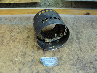
Since I have the motor apart, I figure I may as well clean it up properly, and give the frame a decent paint job. What passes for a factory paint job on these things is nothing to be proud of, and it's not like I have lots of other pressing things to do.

- - -

I peeled off the I.D. label with the help of a heat gun and paint thinner.


 I don't know how I'll ever get the label back on, but I'll worry about that later. Compressed air got the inside of the frame with its stator/windings reasonably clean. Lacquer thinner cleaned up the outer surface, and took off a good deal of the factory paint. Here's the motor frame propped up on an empty tin on a turntable, ready for a primer coat.


I stuffed in a sheet of paper toweling up top, to mask the stator/windings. Here goes.


And that's beginning to look like a credible paint job.

Two coats of black enamel to follow, and it'll be done.

- - -

Here it is, fully painted.


I'll set that aside for the paint to harden for a week, then I can reassemble the motor. Meanwhile, there's still the mount portion of the motor to be painted.

- - -

The Motor Mount

Some things just don't inherently lend themselves to being supported for spray painting, so a little modification is in order.


I drilled and tapped a hole, so I could attach a rod for a 'handle'. Now I have a way to manipulate the thing for painting. The motor mount can get the same primer and black enamel treatment that the motor's frame just did.

- - -

And here it is fully primed and painted.


Once I put it all back together, I'll still have a non-reversible motor, but at least it will be a better looking one.

- - -

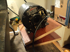
All Done -- MONDAY, JULY 28, 2014

Here it is all done up and ready to go.


The adhesive on the back of the I.D. label was still somewhat effective, so I just stuck the label back on.

That wasn't a difficult job to do, and the results were well worth the effort. There'll be no more shabby looking motors on equipment from this shop.

# # #


# # #
Tuesday, July 15, 2014

An Improved Cotter Pin Installation Method


This method won't work as a retrofit to an existing cotter pin installation, but if you're fabricating a new wagon axle or some-such, it's worth considering.

In a typical cotter pin installation. the pin ends up bearing directly against a sometimes-rotating, thrust-bearing element of the assembly, like so.


By giving the cotter pin a collar to fasten, such as a bored-out hex nut, all rotation load is removed from the pin.


The pin only has to secure against a direct thrust (shear) load; any rotation load is borne by the face of the collar.

Note that unless you take extraordinary care with your machining work, you won't end up with a collar that will fit the shaft/pin either way round. Mark the orientation that goes together with a centre punch, to facilitate future disassembly/reassembly.


# # #

FEEDBACK

# # #

Sunday, July 13, 2014

Painting A Wire Wheel Machine


I've recently built a wire wheel machine, and I'm quite pleased with how it turned out.


But it's begging for a paint job.

If I leave it unpainted, it will forever look like a bunch of cobbled-together junk. If I paint it all properly, it will look like the Cadillac of wire wheel machines that it truly is. So, I'll paint it all properly. I'll start with the mandrel.

- - -

The mandrel came apart easily with only light hammering from a plastic-headed mallet.


That simplifies things a lot -- very little masking will be needed to make the casting paint-ready.

Suspending or supporting objects for spray painting them is often challenging. As it's turned out, the casting lends itself to being suspended fairly easily. A big washer and a wire hook are all that I'll need.


The washer and hook provide me with this arrangement.


And that makes the casting readily paintable. I just have to mask the machined surfaces where the bearings' outer races reside.

- - -

Here's the mandrel casting painted.


That's one coat of primer, and two coats of Tremclad grey. The wire wheel machine is on its way to being gorgeous.

I'll set that aside in a safe place for the paint to harden.

- - -

The Switchbox Post -- THURSDAY, JULY 17, 2014

Here's the post all painted.


The post got two coats of Behr No. 75 latex primer, followed by two coats of Tremclad grey.

Note that installing a long, protruding woodscrew in a concealed part of a thing to be painted can give you lots of ways to support/manipulate the thing. I make frequent use of that method when painting items.

- - -

The Motor -- FRIDAY, JULY 18, 2014

These things are fairly straightforward items to dismantle and paint.


Note that the motor mount cradle is not symmetrical -- it's longer at the left than at the right. Some cradles are symmetrical; some aren't. That's the sort of detail one needs to watch out for whenever one is dismantling a piece of machinery.

Note also that I've scribed alignment marks for the motor's end caps.


Come reassembly time, there'll be no guesswork when aligning the end caps with the frame.

Removing two screws permits the start capacitor cover to come off, then there are two spade connectors holding the capacitor. There is no polarity consideration related to the capacitor's wire connections; I can just disconnect them with no concern for which goes where.


I've already removed the pulley and the motor mount cradle, so it's time to remove the four tie-rod screws and get the motor apart.


That was easy -- the bearings are slip fits on the shaft ends. Not all ball bearing motors come apart so easily. (Dealing with the possible complications is beyond the scope of this post; some other time.)

Note the two thrust washers left behind on the rotor's shaft. Always be watchful for such items when dismantling a motor. Some motors will have none; some motors will have an asymmetrical complement of washers. You always want to note the arrangement, and get the motor back together exactly as it was.

The wiring connections are mostly soldered,


so I'll detach the terminal board and thermal breaker, and just let them remain with the stator while I paint the frame.

- - -

Here's the motor frame on top of a coffee can on top of a turntable, ready for priming


Lacquer thinner took the factory paint off completely. I stuffed in some paper toweling up top to mask the motor's innards.

And here it is after a coat of grey primer, and two coats of gloss black enamel.


Now I just have to do the motor mount cradle and the capacitor cover. Once that's all done, I'll leave everything sit for a week for the paint to harden, then reassemble it all.

- - -

Motor Done -- TUESDAY, JULY 29, 2014

Here's the motor finished and back together.


I've also brush-painted the base plank.


And that's it. The machine is ready for final reassembly.

- - -

All Done -- WEDNESDAY, JULY 30, 2014

Here's the fully painted machine back together again.


That looks much better.

# # #


# # #